This is a very straightforward build, as all surface mount components come pre soldered.
Do this before building this module:
Check that you have all components.
Gather all the tools needed (see lists below).
The tools needed for this build are:
Soldering station or soldering iron.
High quality solder (lead free recommended).
Recommended accessories:
PCB holder (makes life much easier).
Knurled Nut Driver Tool (for tightening jack socket nuts).
10 mm hex socket covered in masking tape (for tightening the potentiometer nut).
Got everything? Let’s get on with it!
BACK PCB
1. Power connector
Begin by soldering power header (J1). Make sure it is oriented according to the silk screen!
2. Headers
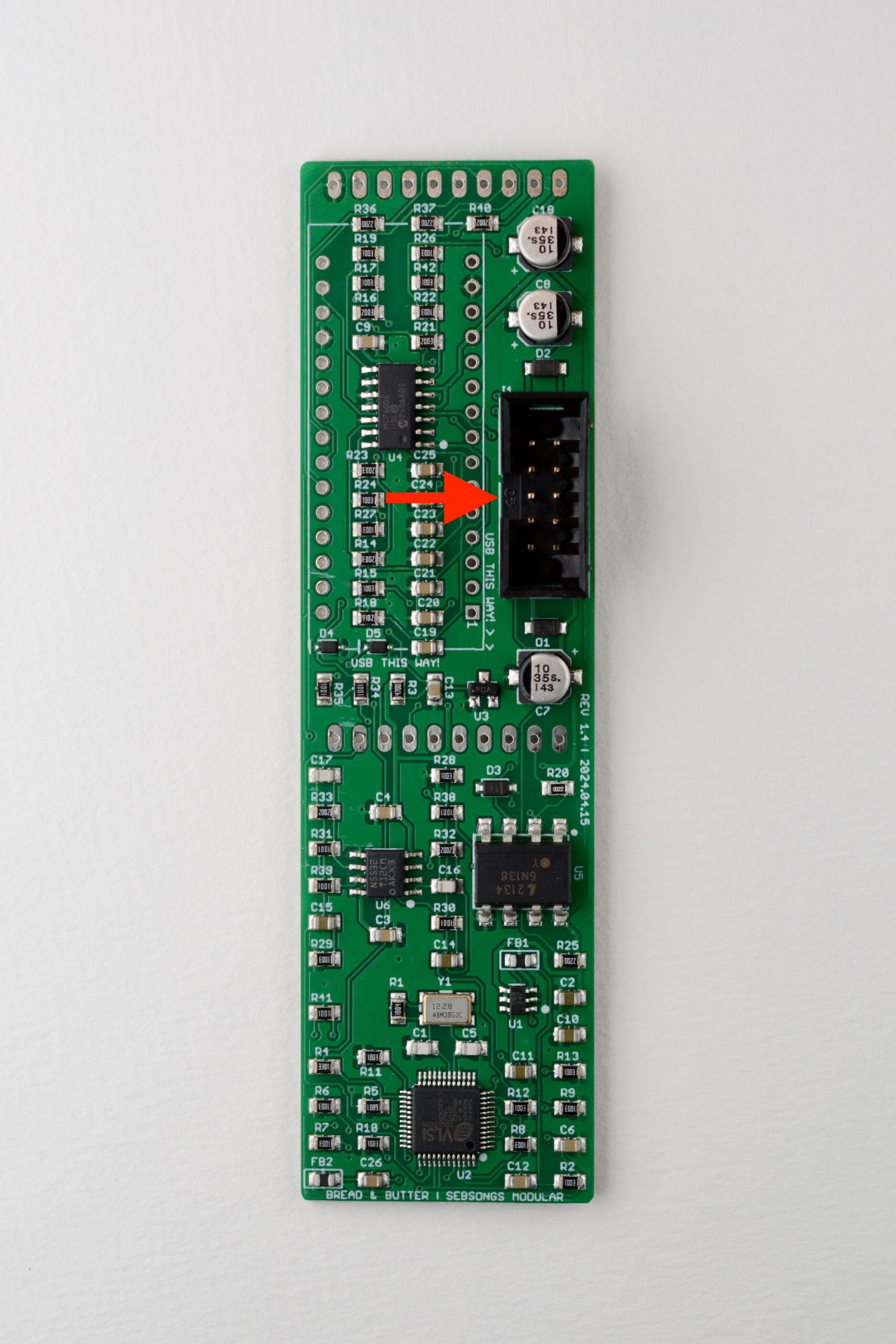
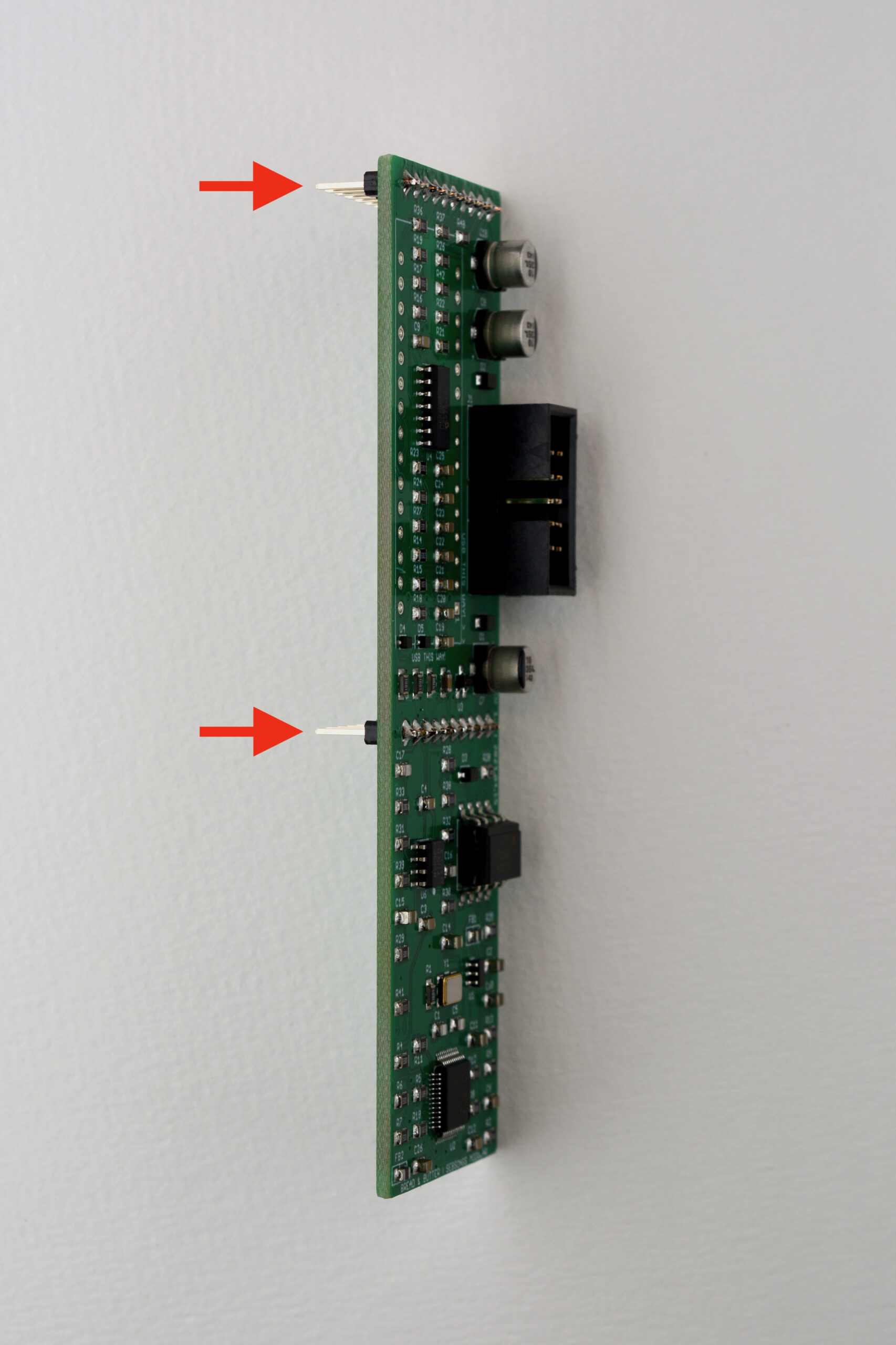
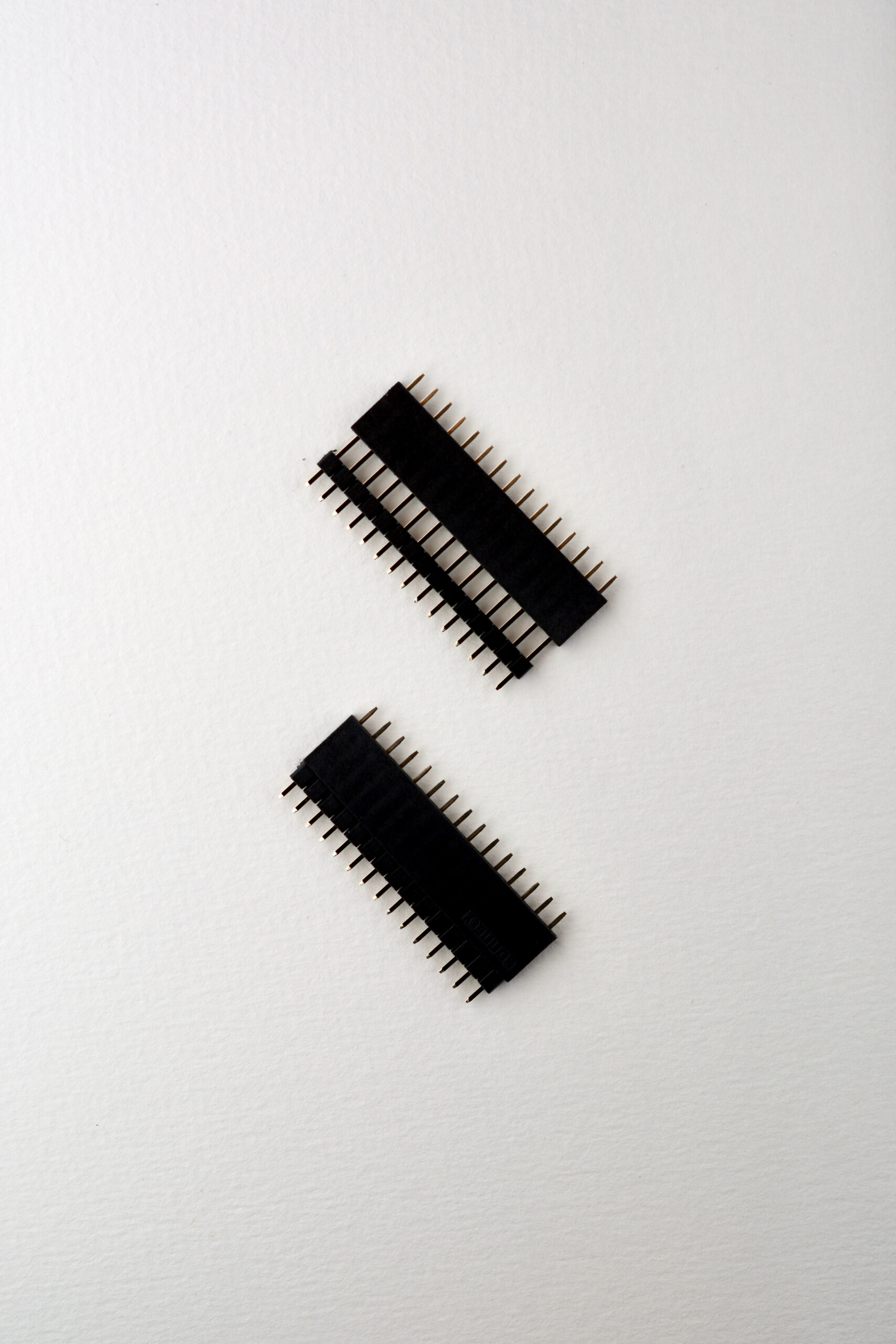
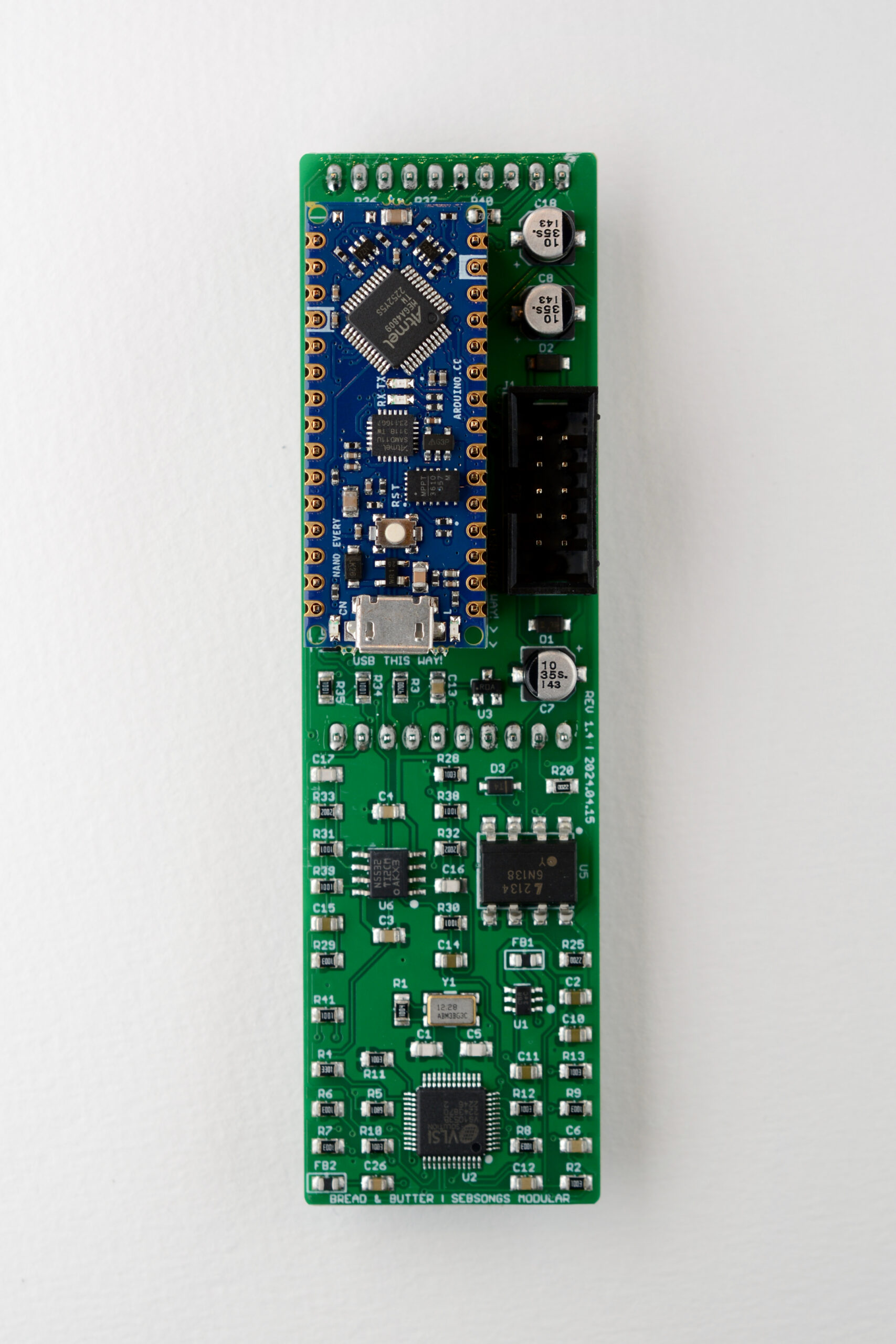
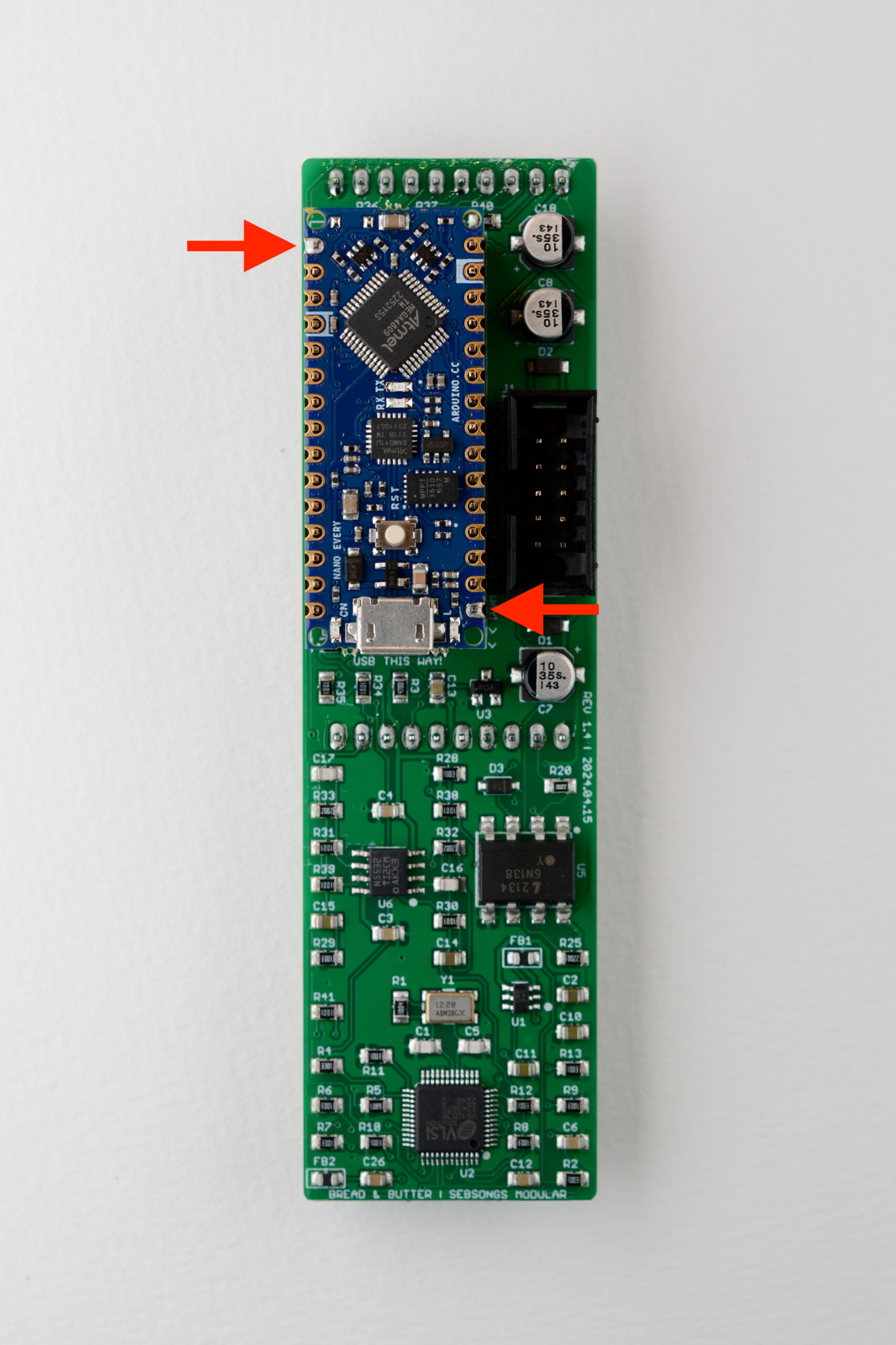
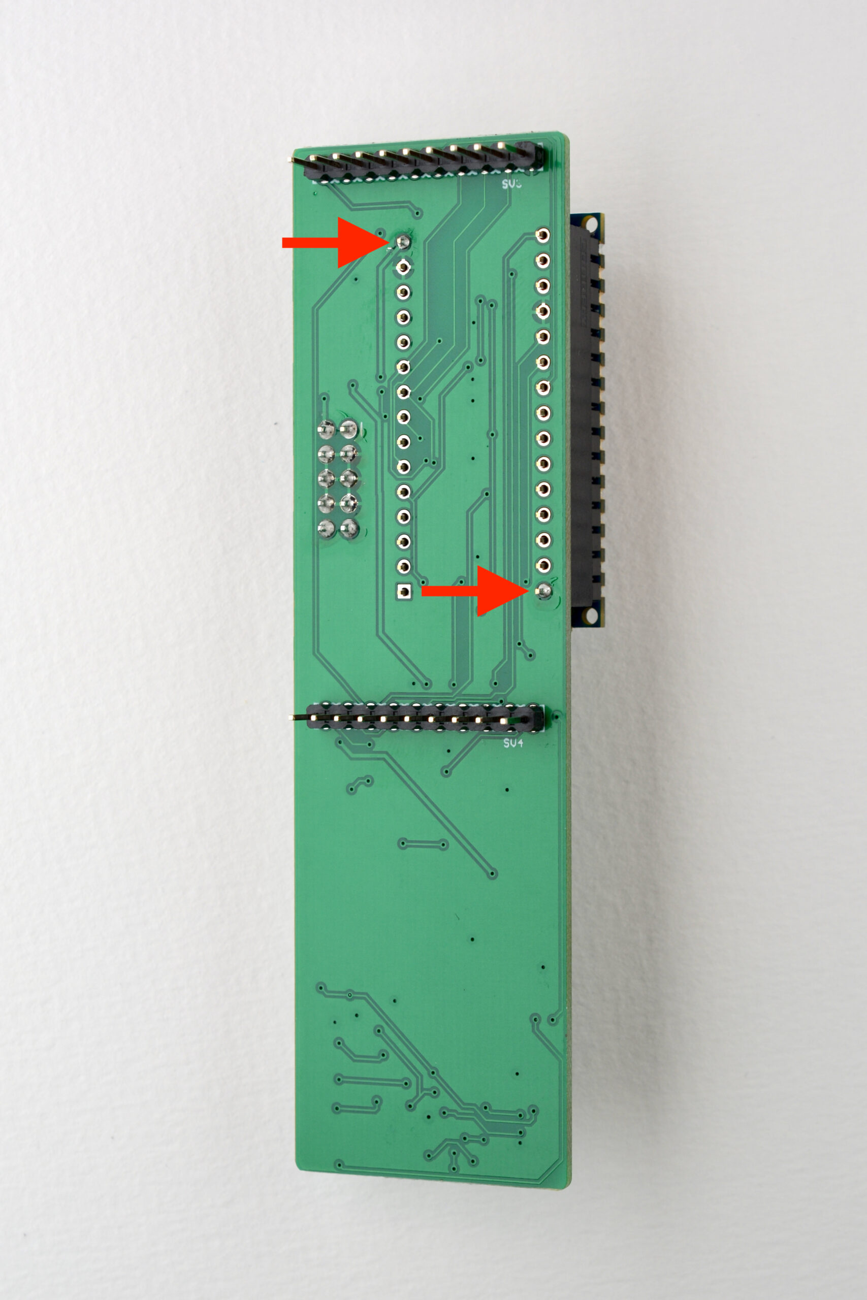
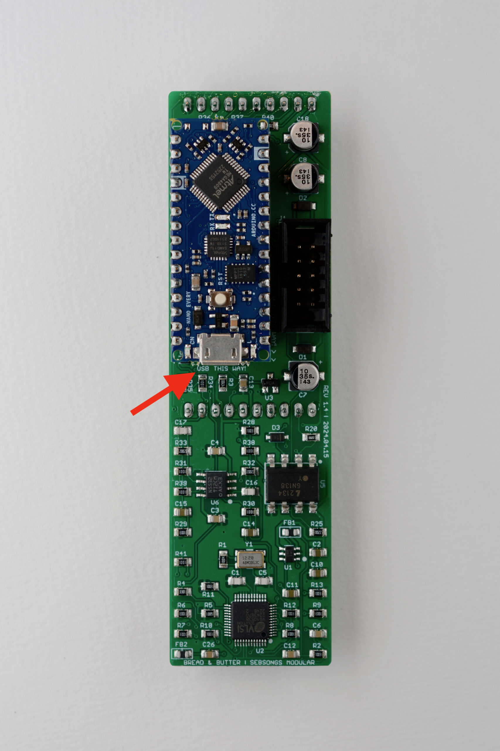
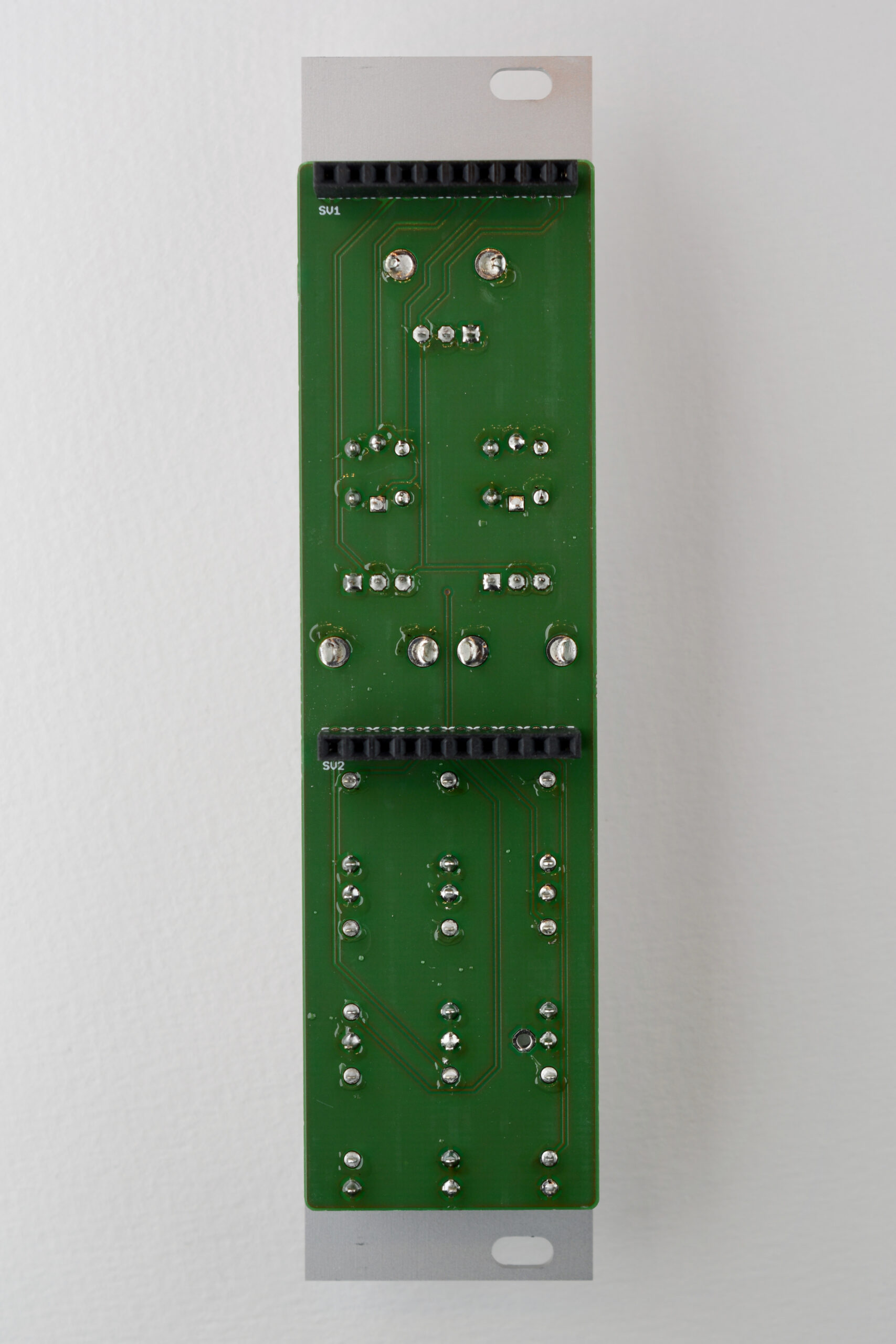
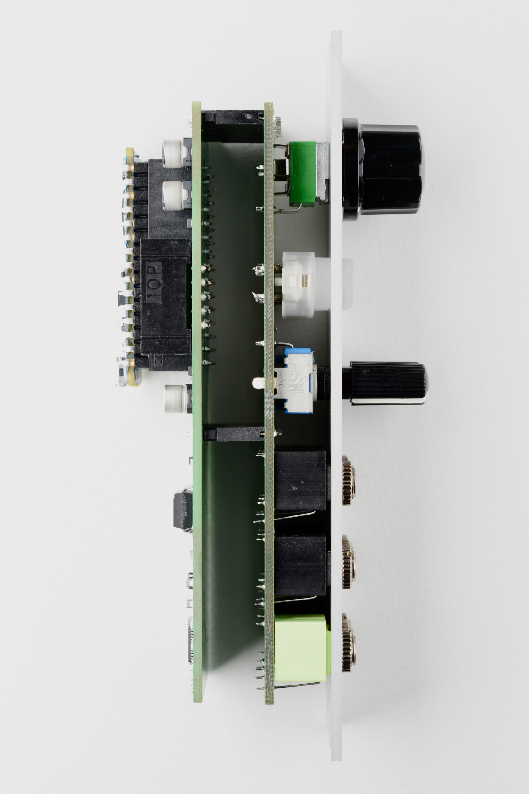
Fit the two 10-pin pin headers (SV3, SV4) from the back of the PCB and make sure they are fitted nice and straight 90 degrees to the PCB. Solder one pin on each header and check again to make sure they are straight. See image for reference.Fit the 15-pin pin headers with the 15-pin sockets as shown in the image.Place the fitted headers on the PCB with the sockets facing down towards the PCB and the pin headers facing up. Place the Arduino Nano Every on the pin headers and make sure it lies flat against the pin headers.Tack the Arduino in place by soldering two corner pins.Do the same thing on the PCB. Check that the pin headers, sockets and Arduino are flush with the PCB and everything is at a 90 degree angle.Solder the rest of the pins on the Arduino and the back of the PCB. Finally, check that the USB connector on the Arduino is facing towards the “USB THIS WAY!” label on the PCB. If not, pull it out of its sockets and place it correctly.
FRONT PCB
3. Headers
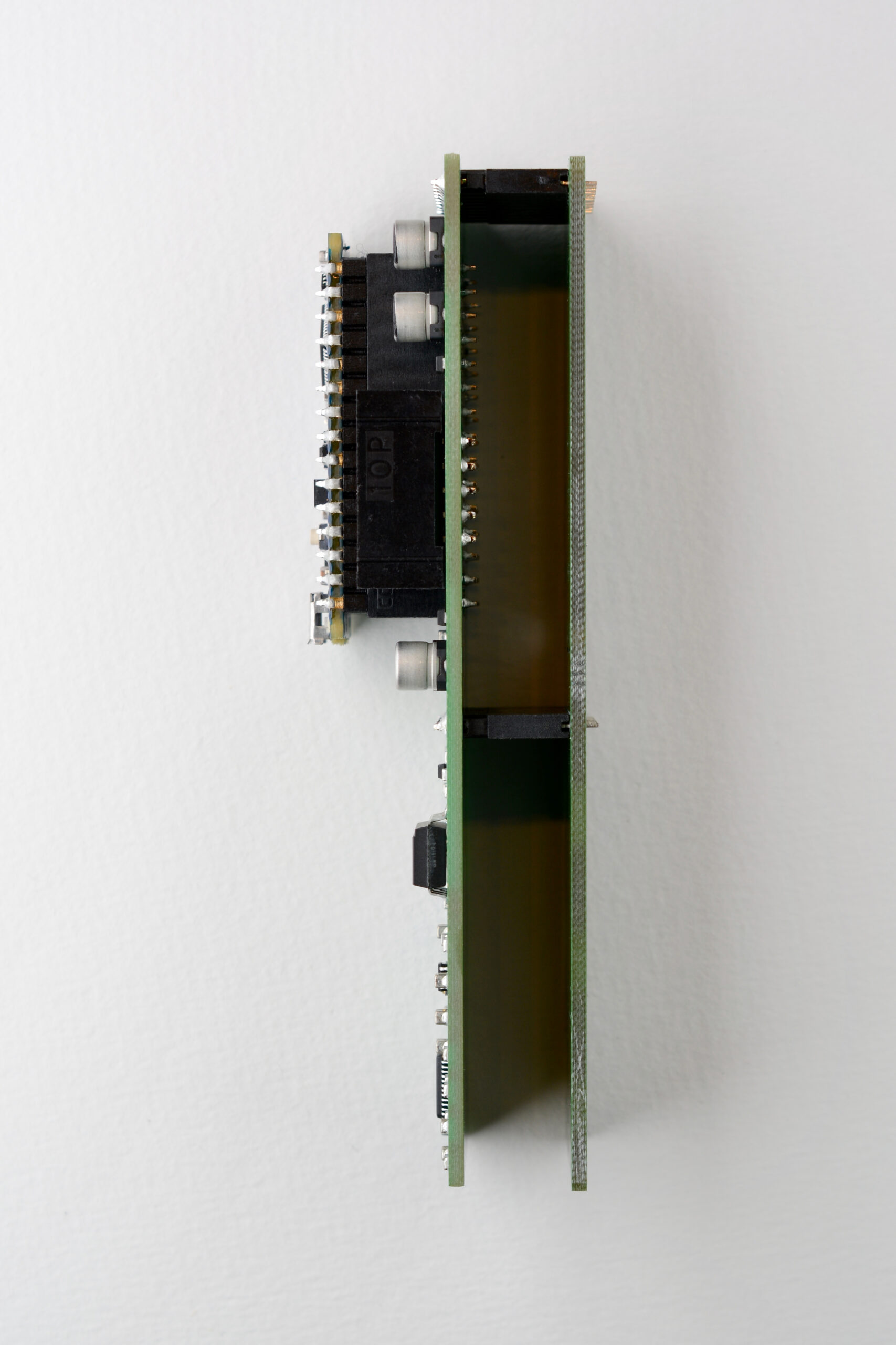
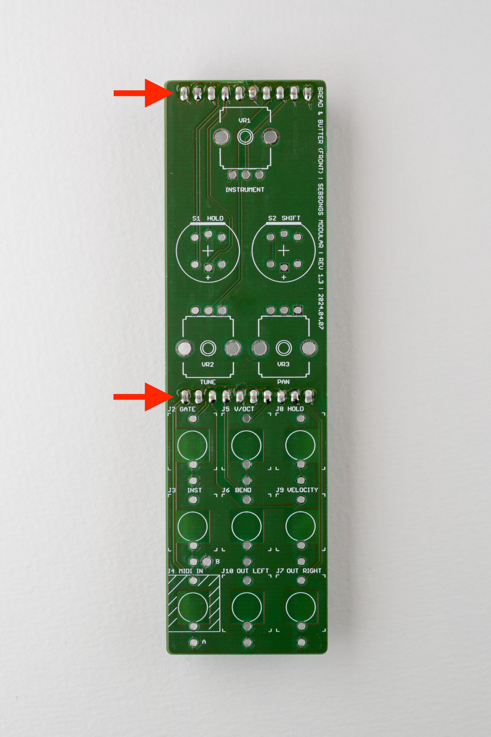
Fit the 10-pin header sockets to the pins on the back side of the back PCB. Then fit the FRONT PCB onto the pins of the header sockets. Make sure the front side of the PCB is facing outwards. Double check that the two PCBs align with each other and that the front side of the front PCB is facing up, see image for reference. Then solder the headers. Finally, pull the front and back PCBs apart and store the back PCB safely for final assembly later on.
4. Panel components
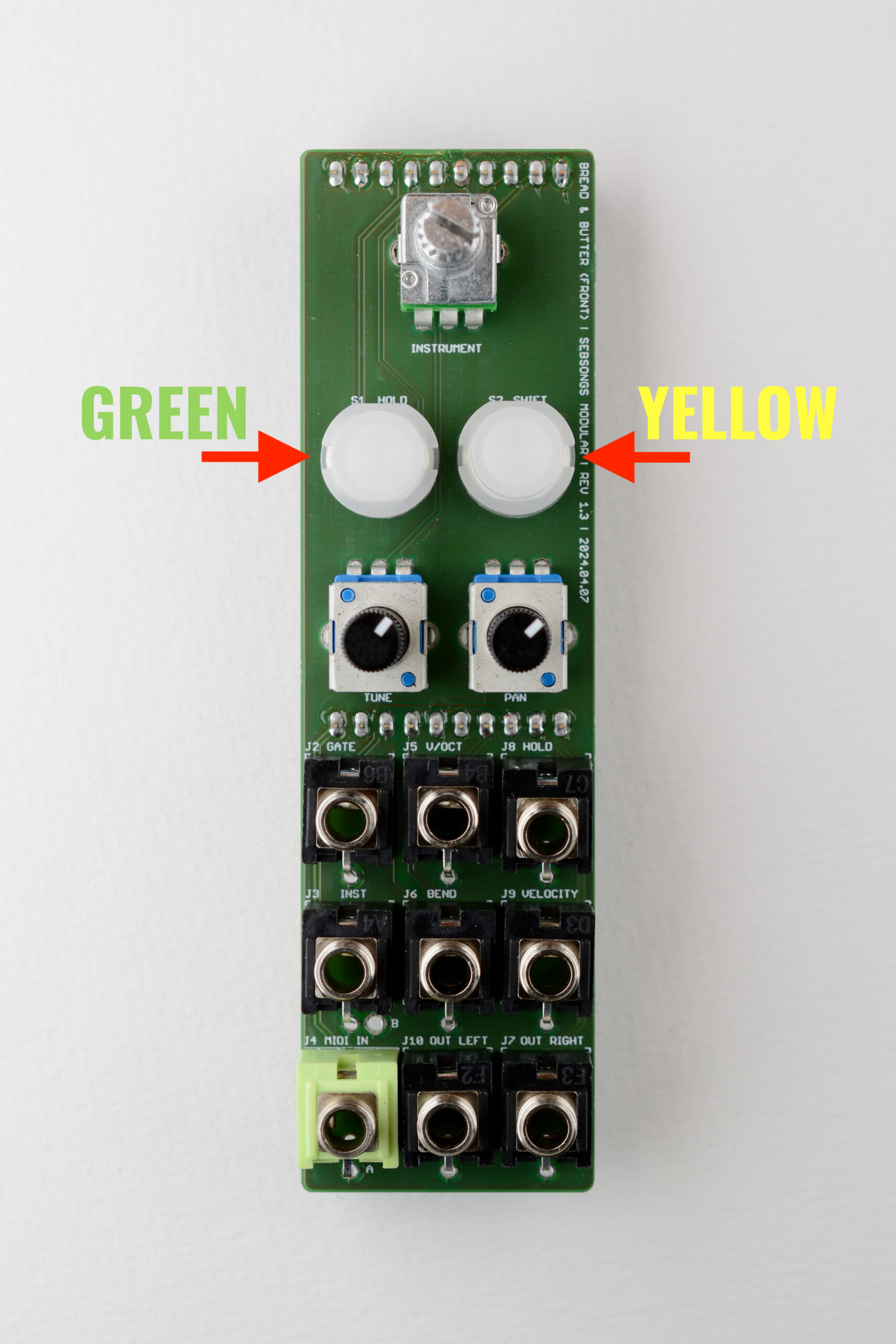
Place all panel components in their corresponding holes on the PCB as shown in the image above. Make sure that the GREEN switch is place on the S1 position and the YELLOW switch in the S2 position. Also make sure that the green stereo thonkiconn jack is placed on the MIDI in position (J4). DO NOT SOLDER ANYTHING YET!
NOTE: The MIDI TRS socket can be configured to accept either the TRS MIDI A or B standard. As shown in the image it is configured in the more common A standard. For MIDI B, turn the jack 180 degrees so the protruding ground pin connects to the hole marked “B”. You might have to bend the other two legs slightly when fitting the front panel in the next step as the jack barrel is not centered on the jack casing, but otherwise this is an easy way to choose MIDI standard in the build process.
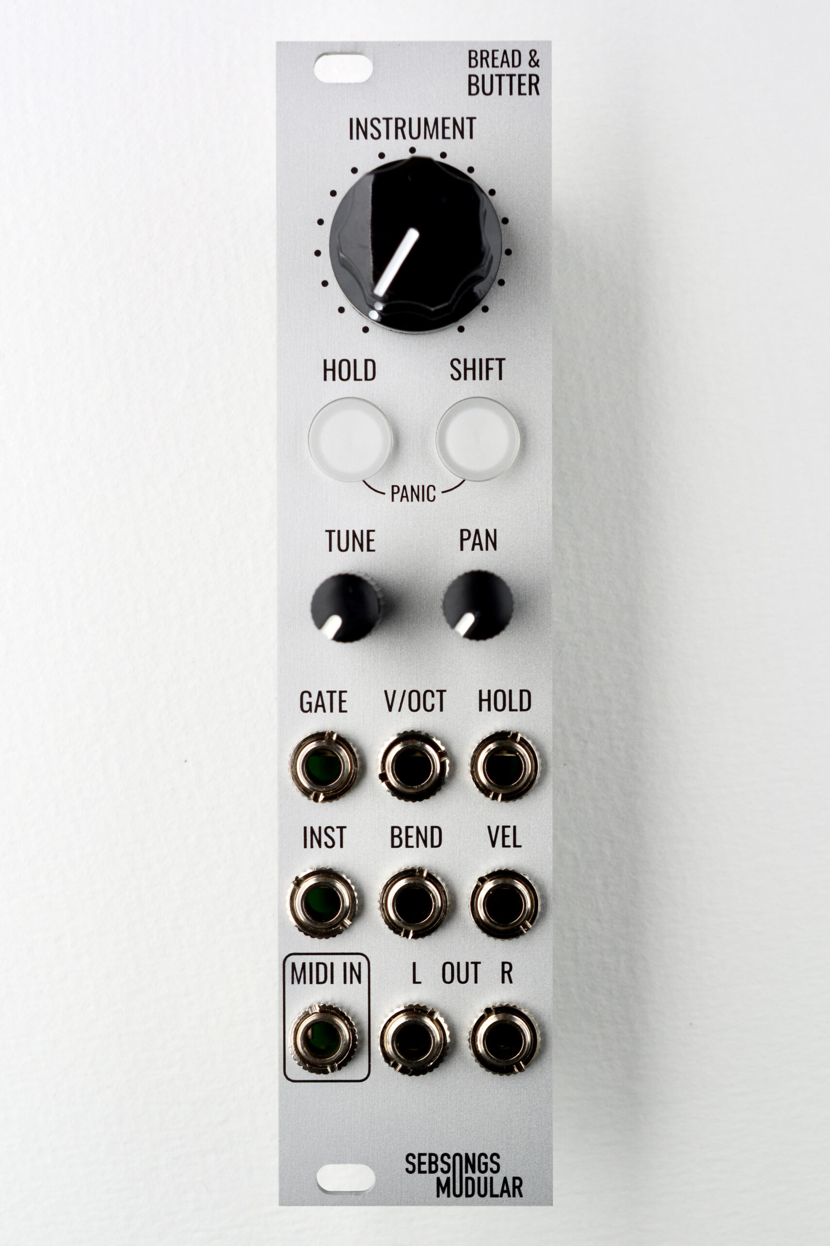
Having a hard time deciding which standard you should choose? Read more about which manufacturers use which standard here. Place the front panel over the jacks, potentiometers and switches and fit all the nuts and washers. Hand tighten all nuts lightly to keep the panel in place.Flip the whole assembly, make sure that everything is nice and straight. Then solder all the solder joints. Make sure to push the switches lightly against the PCB with your finger as you solder them, or tape them in place with some masking tape before soldering them.
5. Finishing up
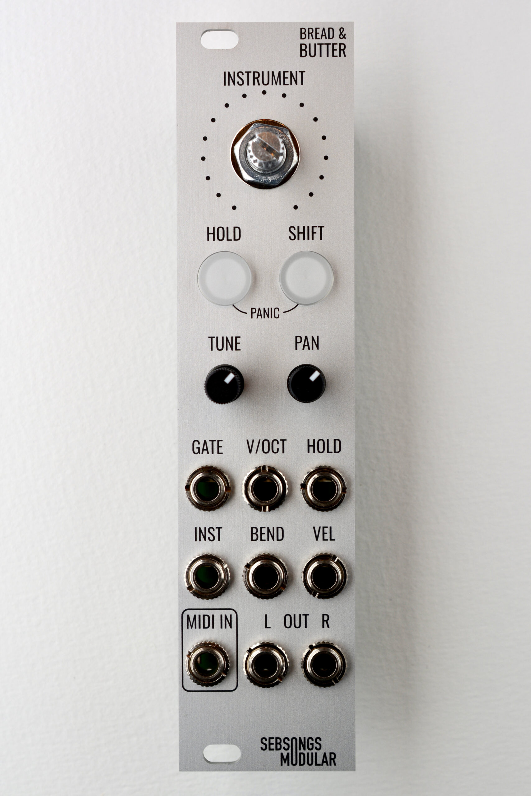
Now you can fit the back PCB to the front PCB and panel assemply.Tighten all nuts with appropriate tools and fit the big knob on the top potentiometer. The tall trimmer potentiometers are flipped 180 degrees, so make sure to fit their knobs accordingly. Turn the knobs all the way down (they look like they are pointing at 2 o’clock) and make sure the indicator on the knob is pointing in the exact opposite direction.
And that’s it, you’re done!
6. Powering up and testing
Before powering on, measure resistance with a multimeter between ground and + and – respectively on the power connector to make sure there are no short circuits. The resistance should be in the Mega Ohms range.
At first power on, the octave setting for the tuning is set to zero because the eeprom memory has not yet been programmed with a value. To fix this, hold SHIFT and turn the TUNE knob to its center position. This is the default octave setting. From now on the module will remember whatever value you set the octave setting to.