This is a quite straightforward build, as all surface mount components come pre soldered. There are some steps that are a little tricky, so have patience and be calm and well rested when you do this build.
Do this before building this module:
Check that you have all components.
Gather all the tools needed (see lists below).
The tools needed for this build are:
Soldering station or soldering iron.
High quality solder (lead free recommended).
Sharp sidecutters.
Snipe nose or flat nose pliers
Recommended accessories:
PCB holder (makes life much easier).
Breadboard for soldering the Raspberry Pi Pico pins.
Knurled Nut Driver Tool (for tightening jack socket nuts).
10 mm hex socket covered in masking tape (for tightening the potentiometer nuts).
Fine metal file for finishing cut headers.
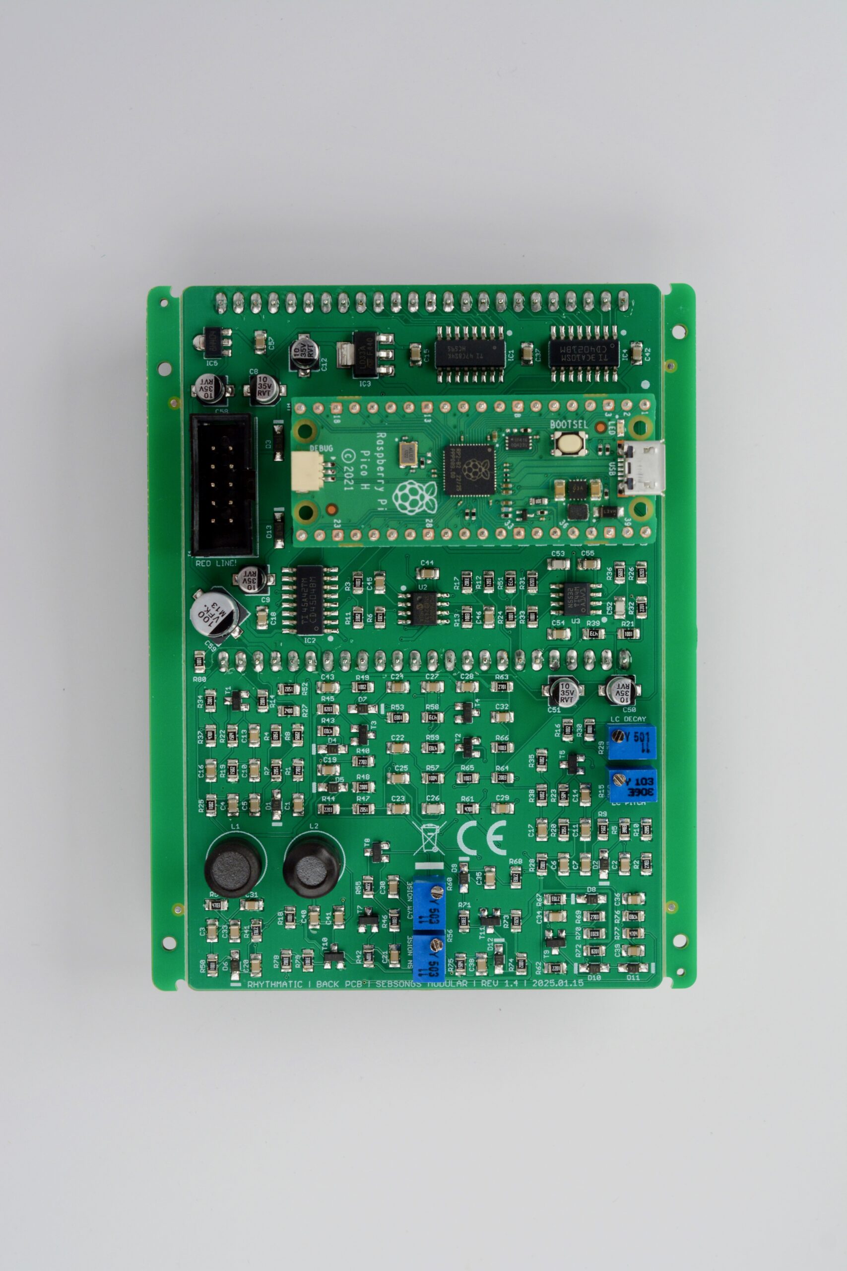
BACK PCB
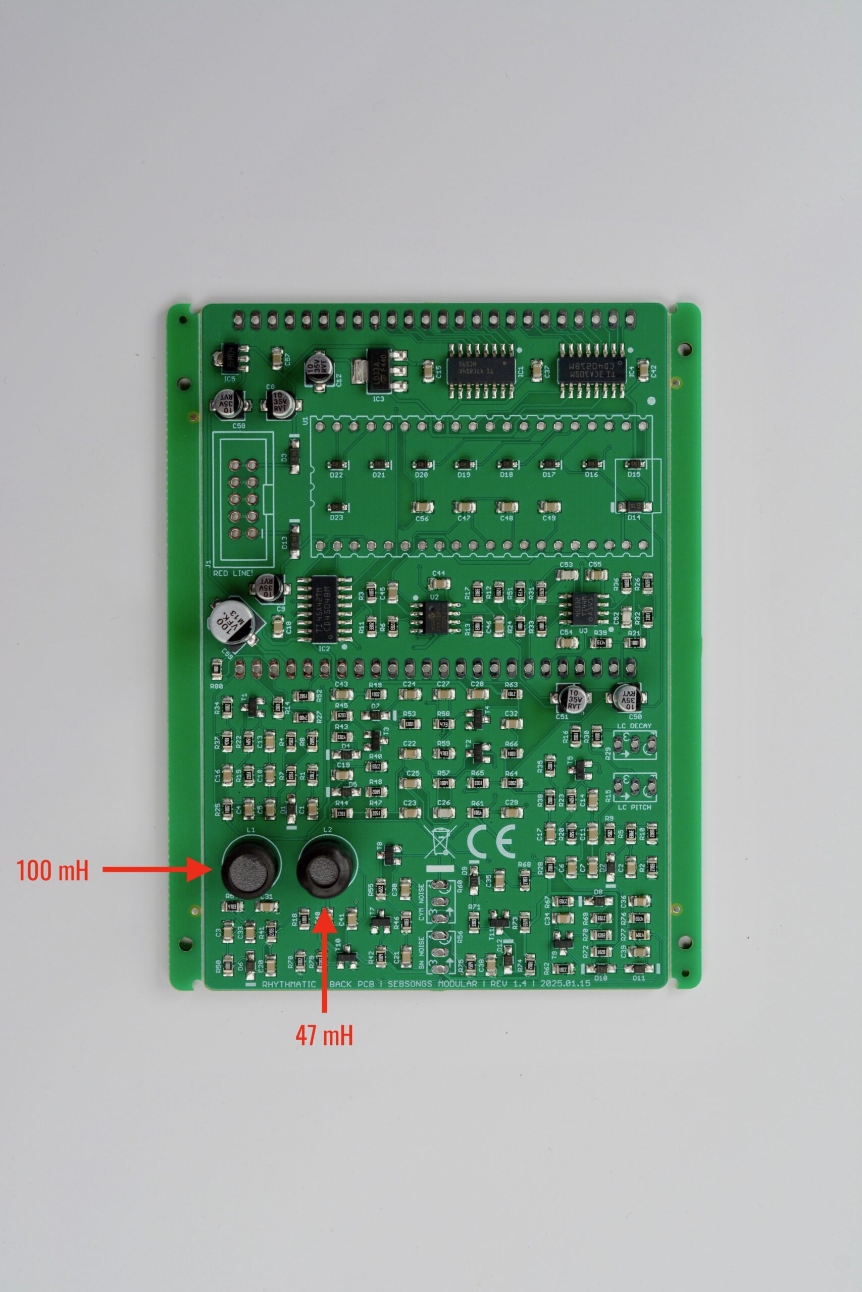
1. Inductors
Begin by soldering the two through hole inductors (L1, L2).
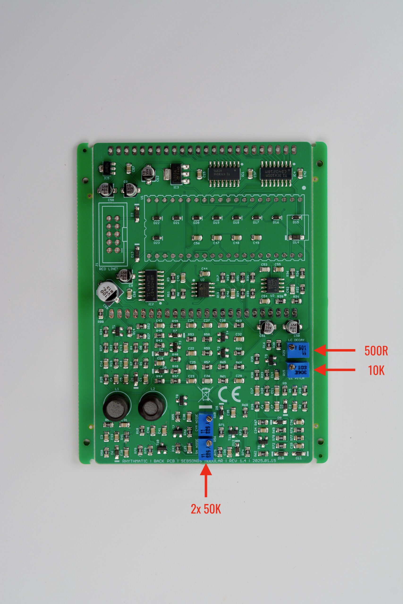
2. Trimmer potentiometers
Fit the trimmer potentiometers in their respective places (R15, R29, R56, R60). See image for reference on where each value goes. To get them mounted straight, solder the center pin first and then align the body of the trimmer potentiometer before soldering the rest of the pins.
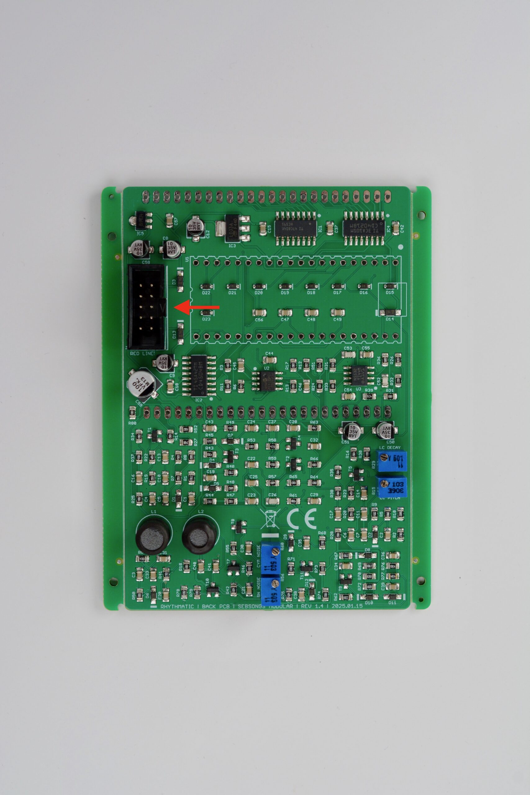
3. Power header
Solder the power header (J1). Make sure it is oriented according to the silk screen! See image for reference.
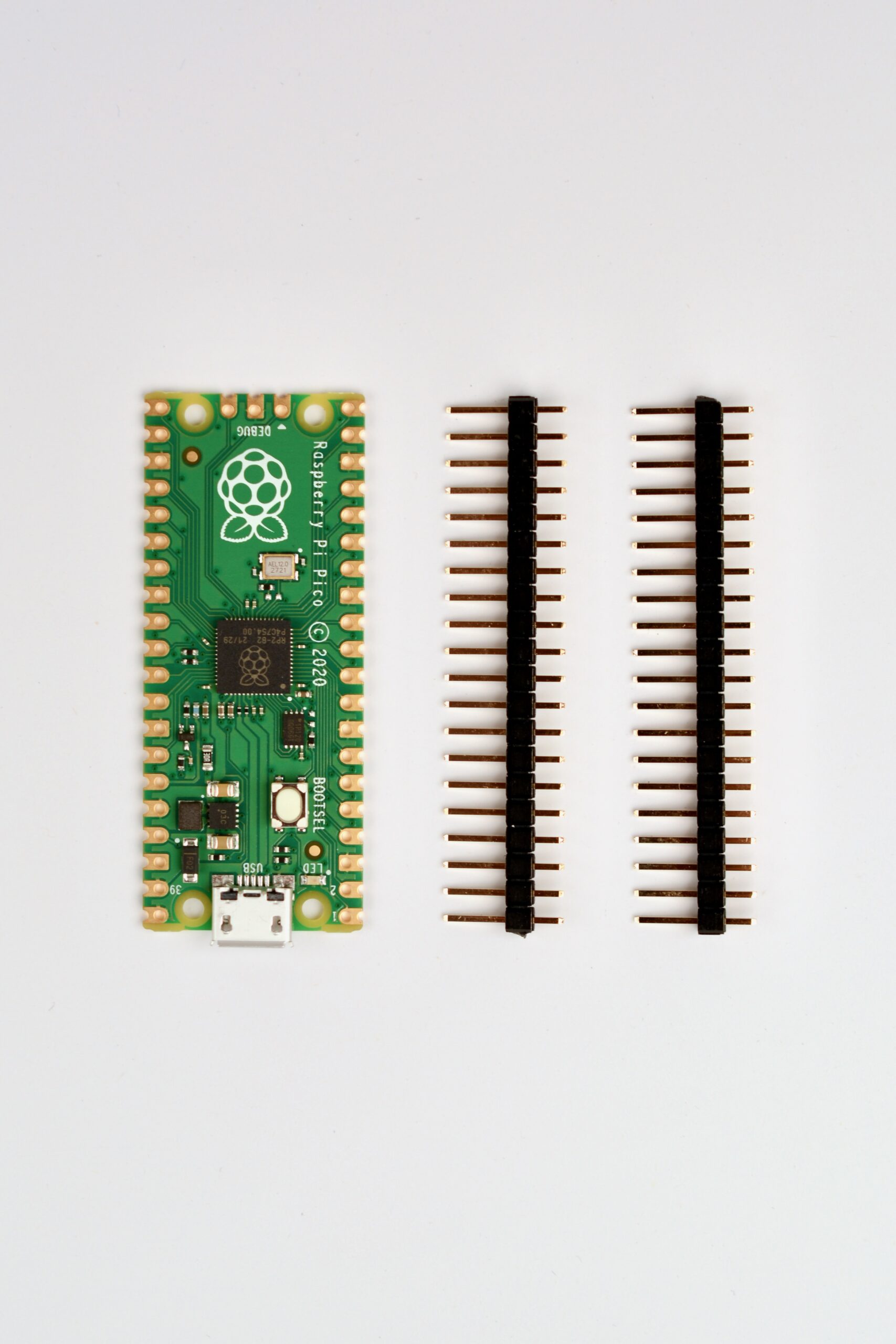
4. Preparing the Raspberry Pi Pico
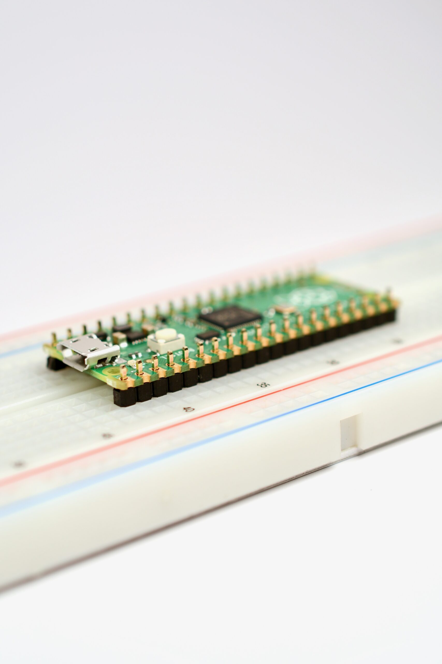
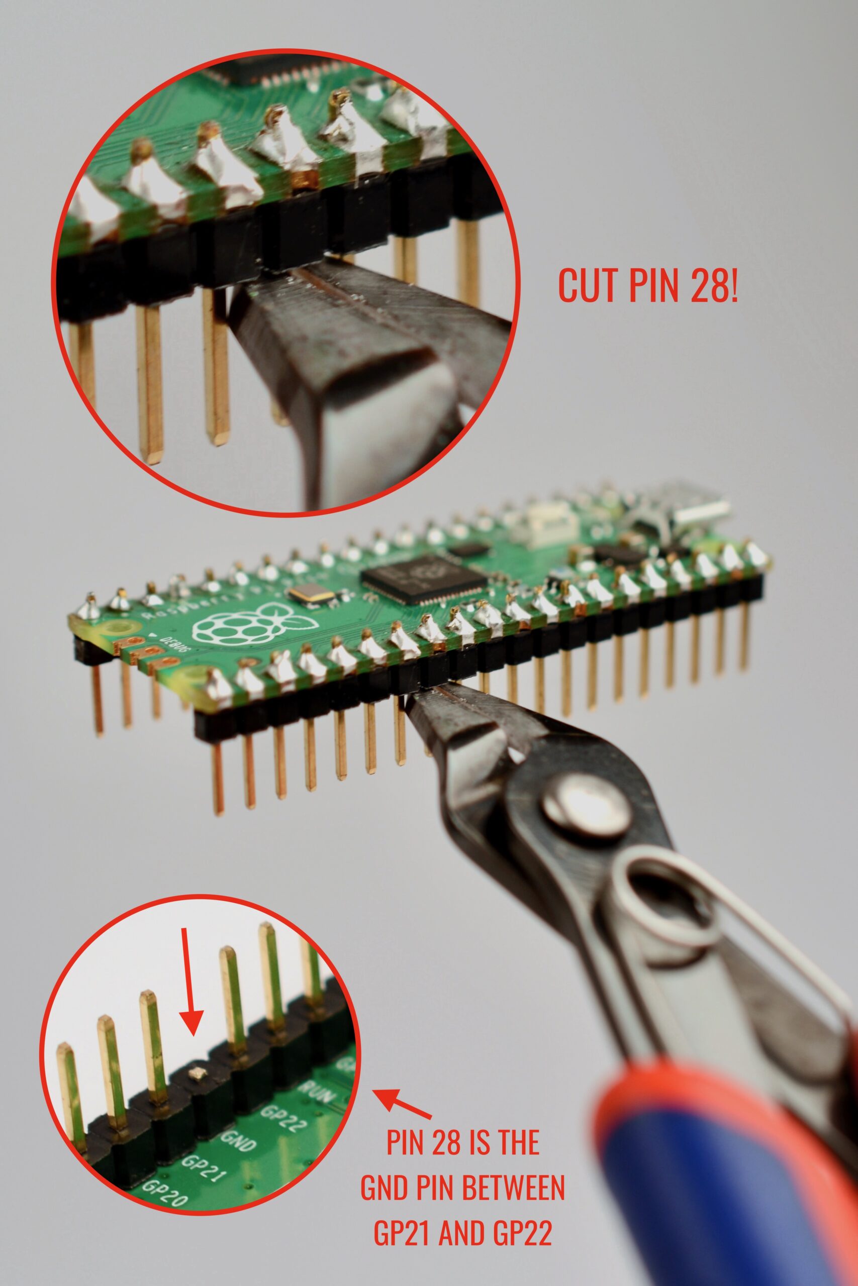
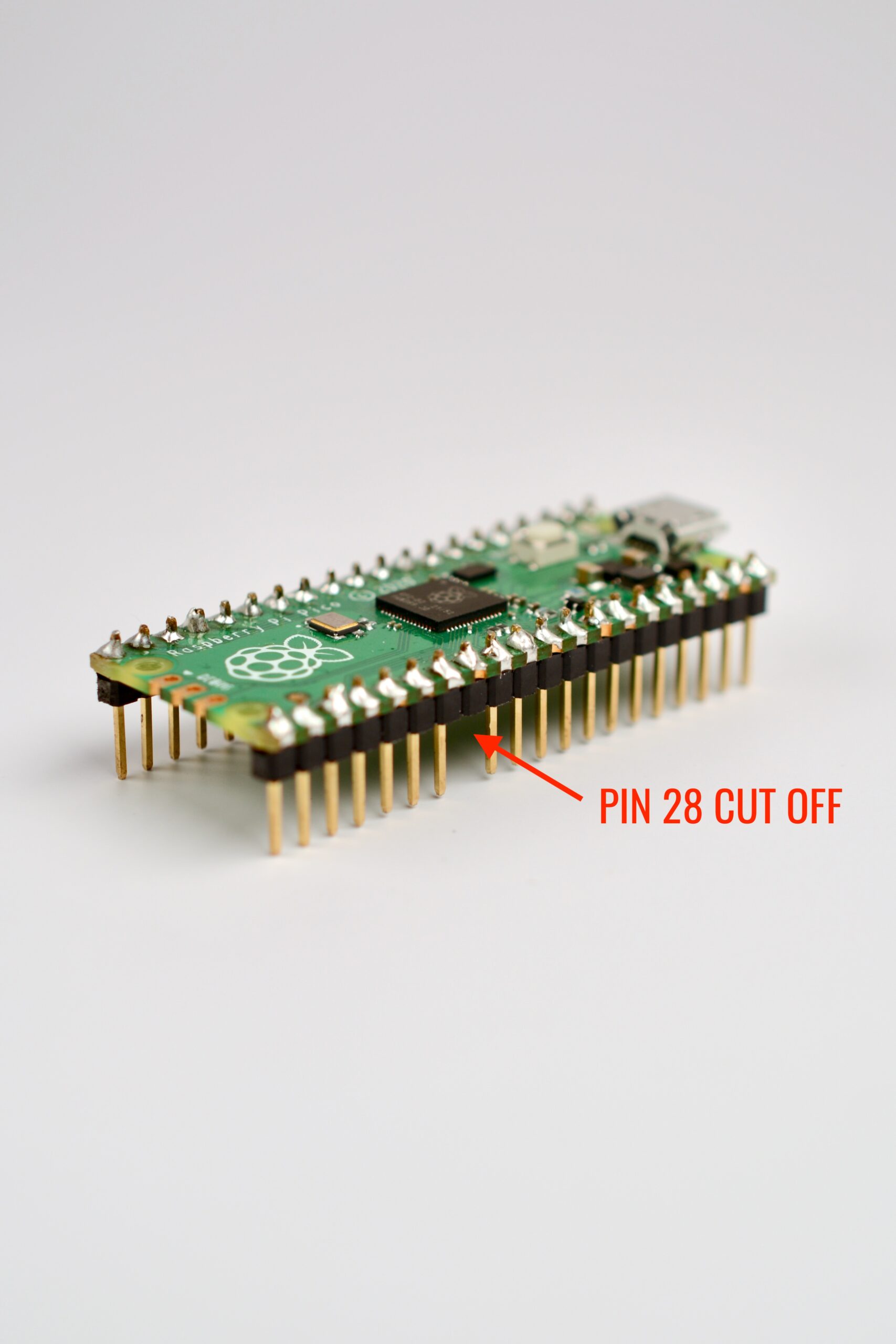
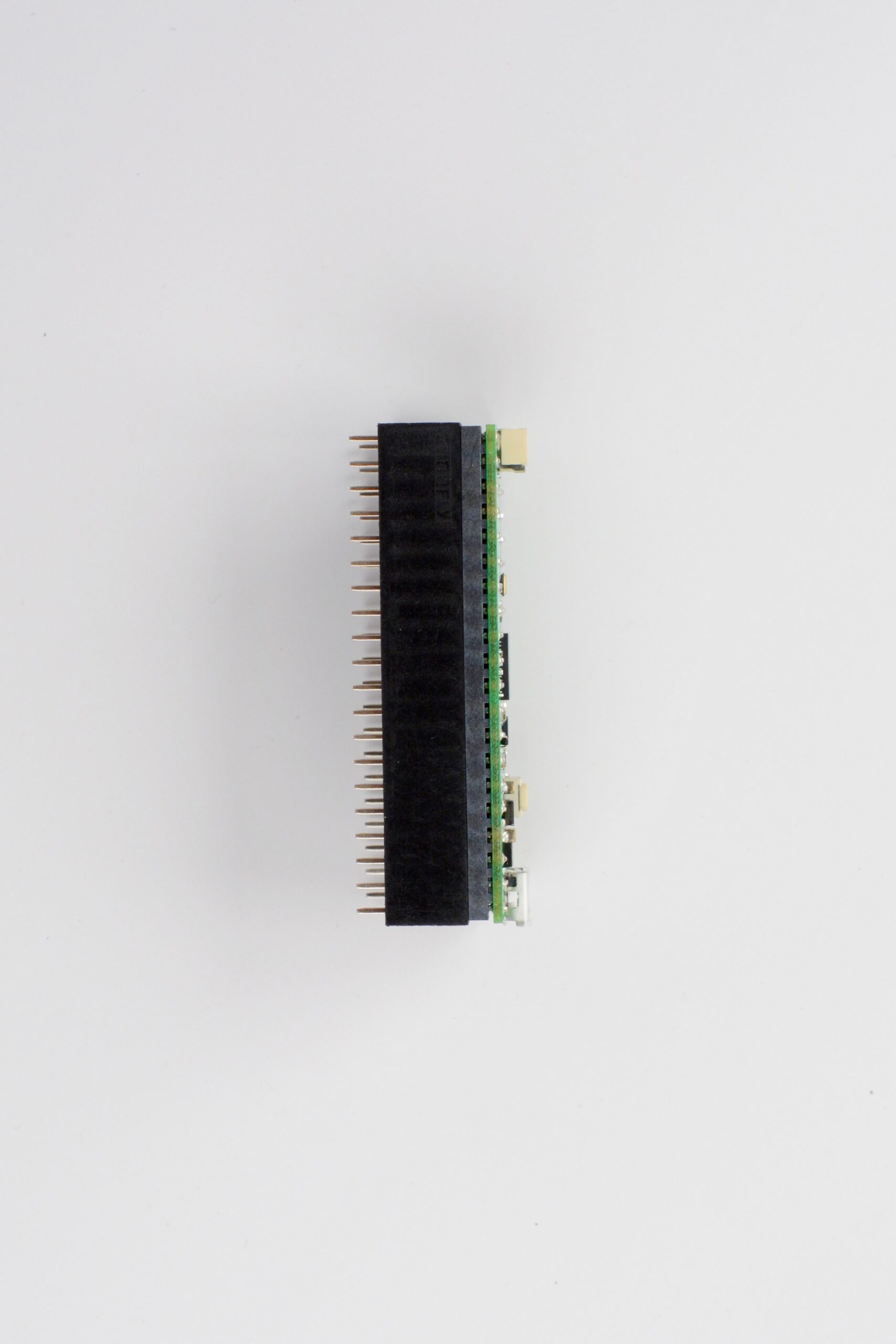
Locate the Raspberry Pi Pico and the two 20 pin male pin headers.Seat the male pin headers in a breadboard and fit the Raspberry Pi Pico on the pins, making sure it is seated flush with the pin headers – see image for reference.Solder all the pins! Note that in the next step, you are going to cut off Pin 28 from the Raspberry Pi Pico. If you want, you could skip soldering that specific pin and then just pull it out of the header when all other pins have been soldered. If you want to cut it instead, follow the instructions below. It doesn’t matter which way you do it, just make sure Pin 28 gets removed somehow.Pin 28 on the Raspberry Pi Pico needs to be cut off before mounting it to the female headers. The pin is marked GND on the bottom side of the Pico, and it’s located between then pins marked GP21 and GP22. Use a pair of side cutters and cut it off as shown in the image.The Raspberry Pi Pico should look like this after pin 28 has been cut off.Now fit the 20 pin female headers onto the pin headers of the Raspberry Pi Pico.
5. Soldering the Raspberry Pi Pico
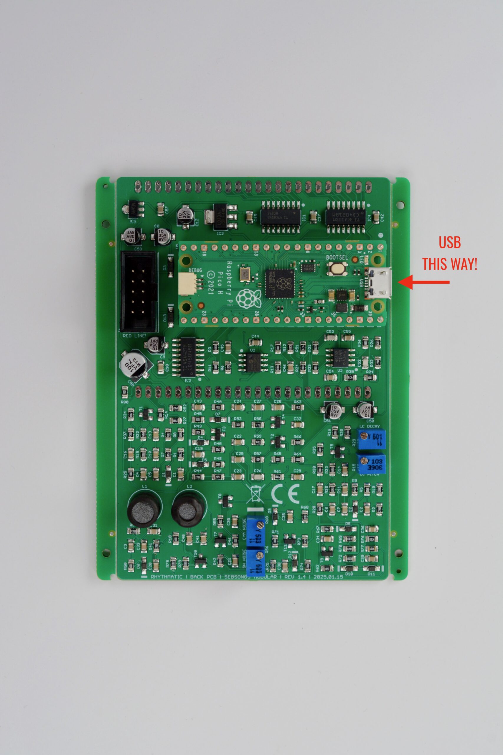
Fit the Raspberry Pi Pico assembly on to the PCB (minding its orientation, see image) and solder two diagonally adjacent corner pins. Check that the all the pins are flush with the PCB and everything is at a 90 degree angle. Then solder the rest of the pins.
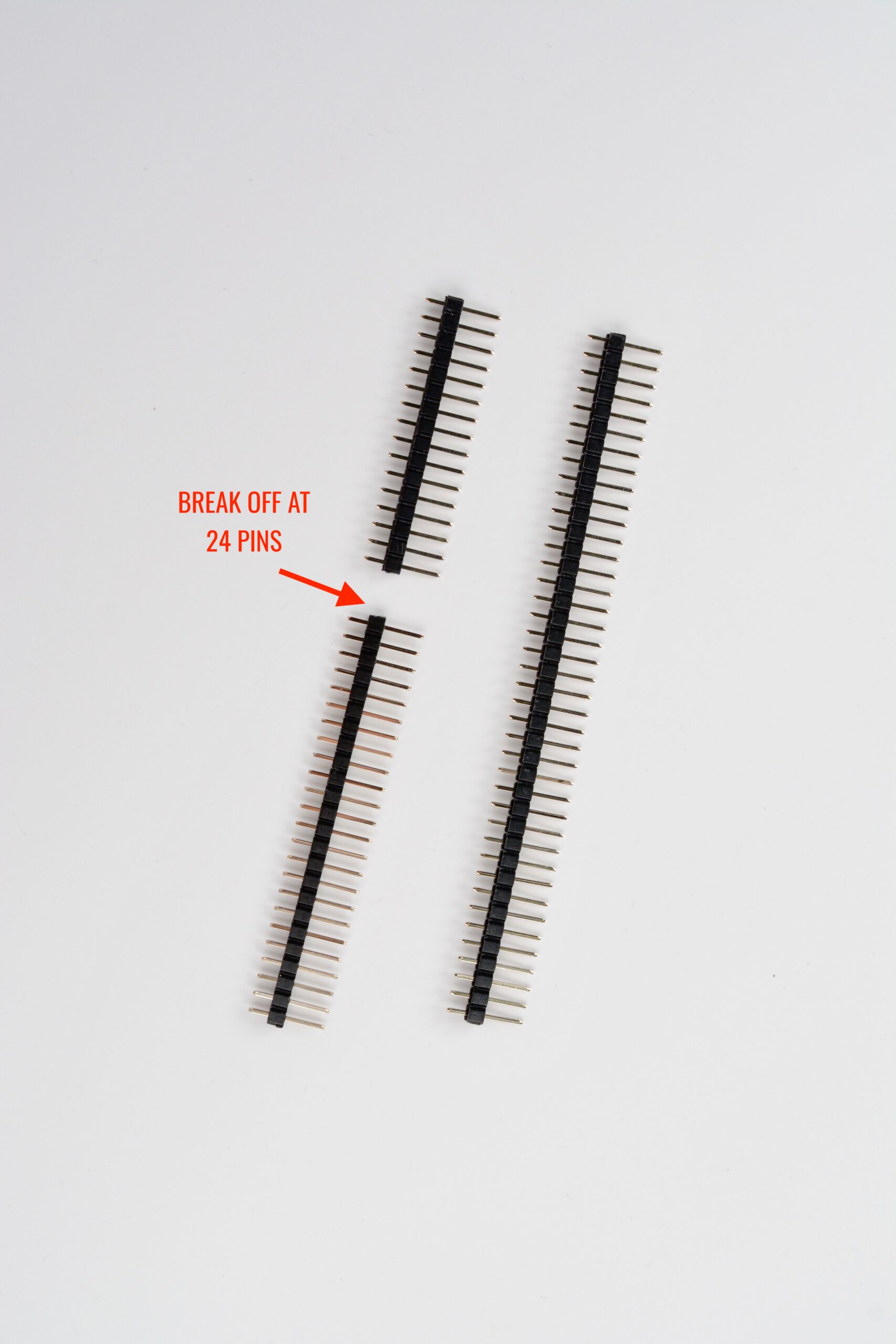
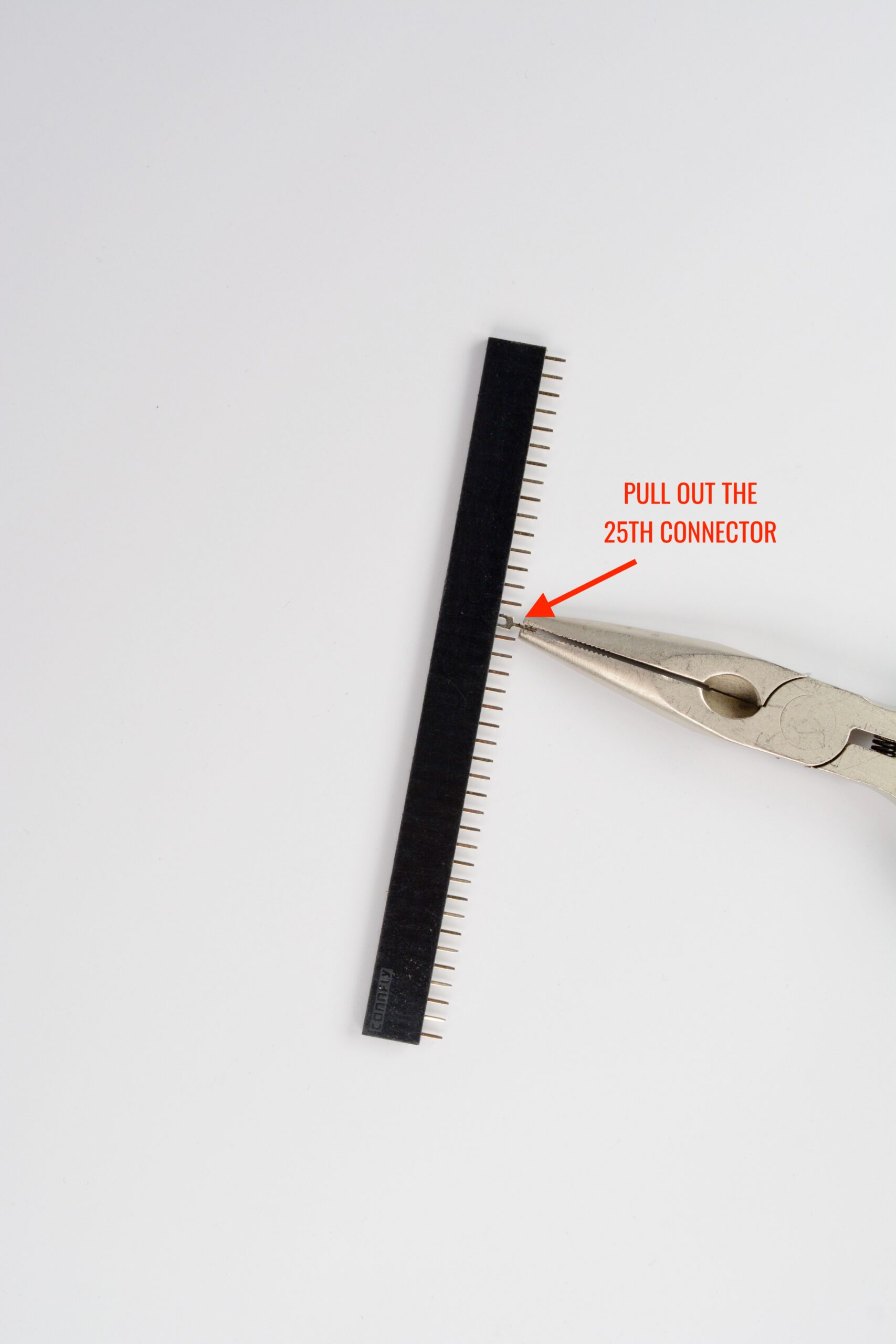
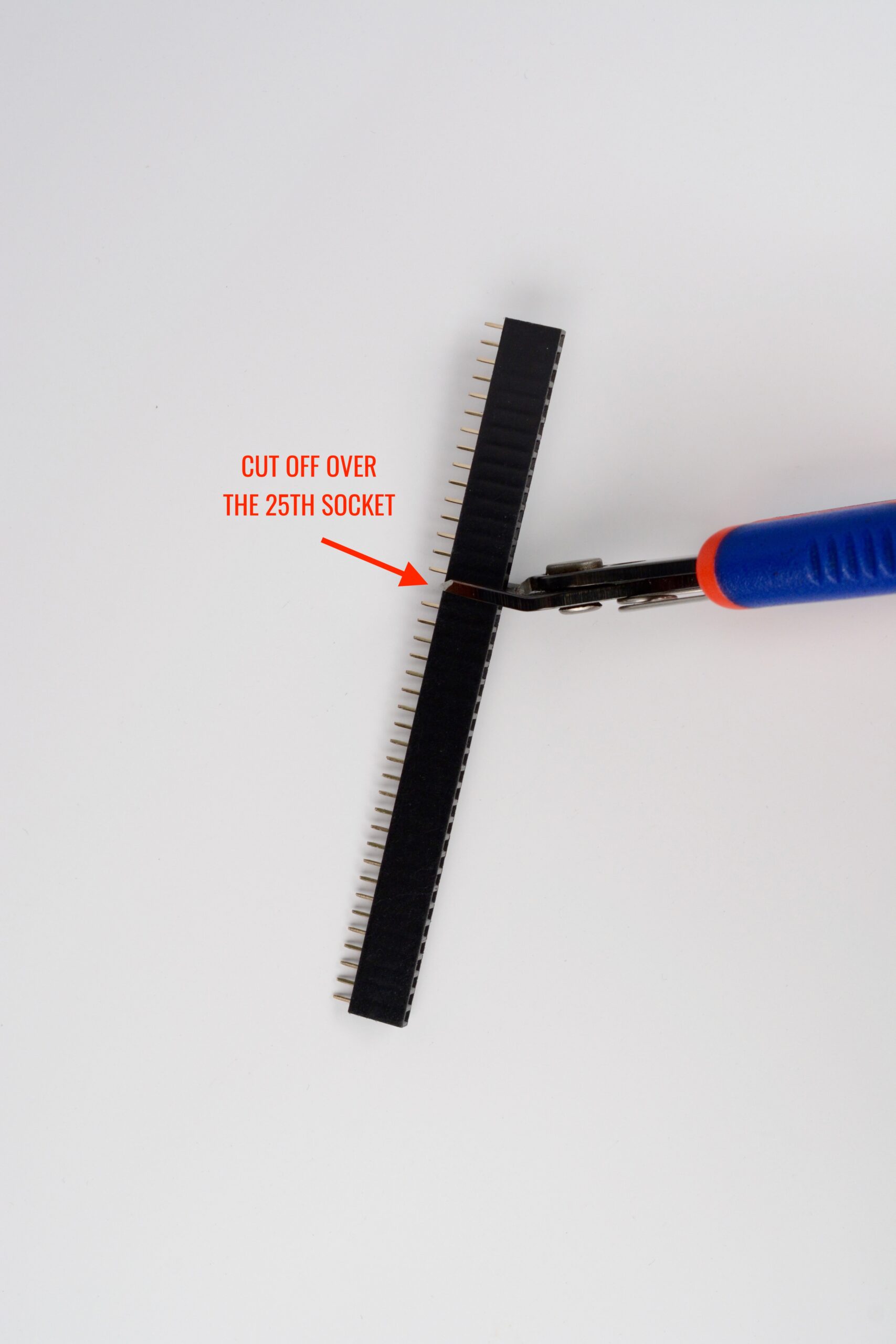
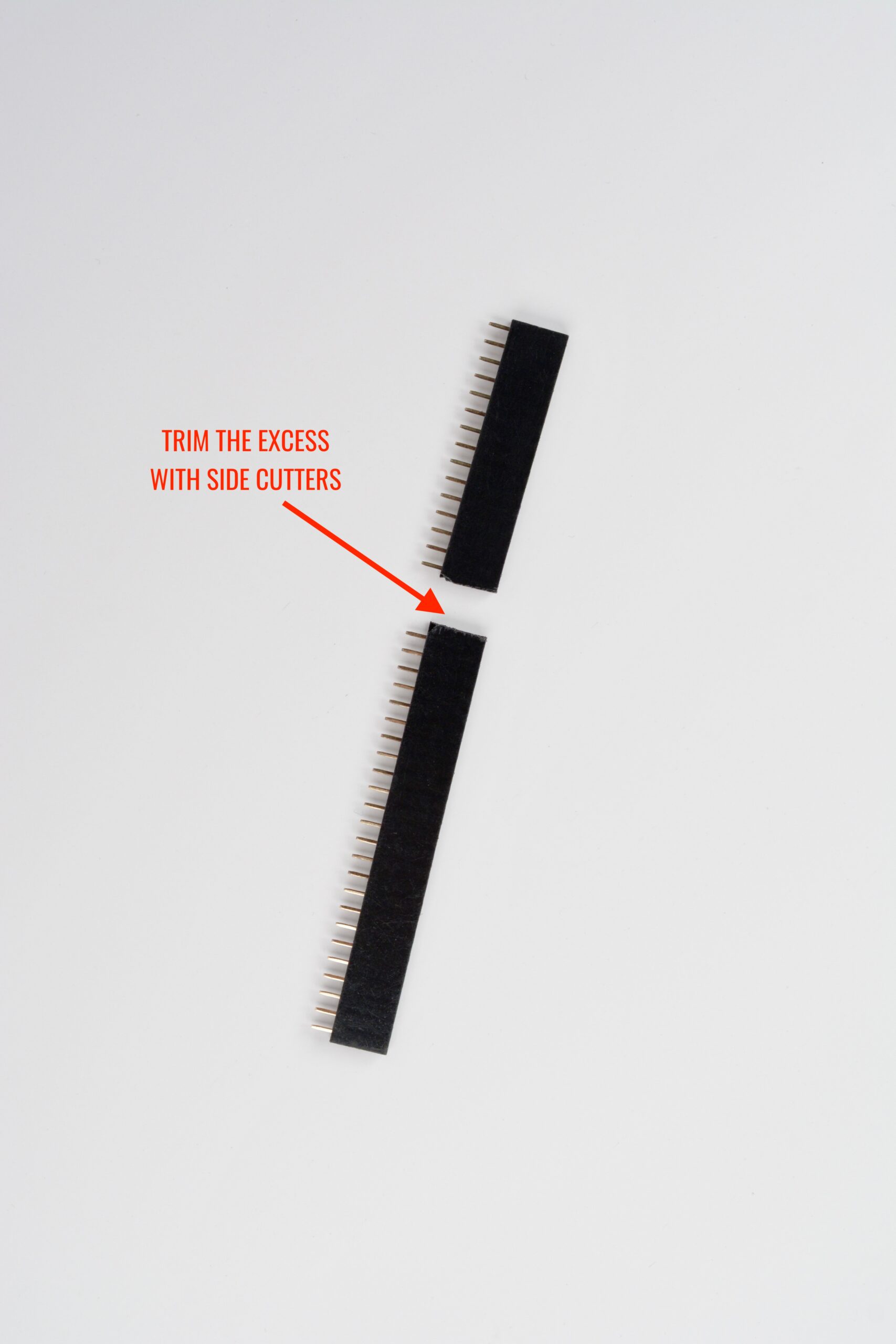
6. Preparing the 24 pin PCB interconnect headers.
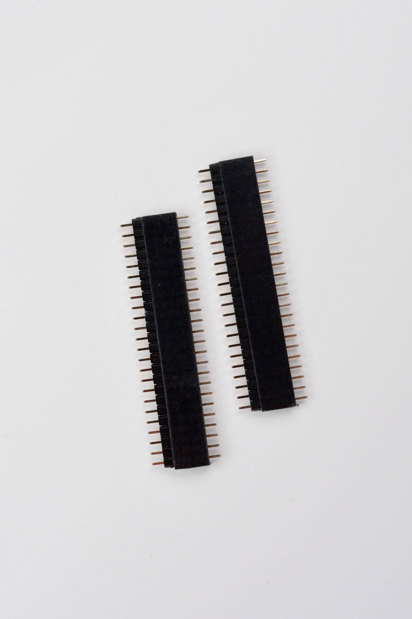
The kit comes with male and female headers that have more pins than is needed, so we need to trim them. The male pin headers can simply be broken off using your fingers, or a pair of pliers and you fingers. Count the pins twice before breaking it, and compare with the connector on the PCB. Save the excess pin headers for another project!The best way to cut the female headers is to first pull out the connector pin next to the last pin you want to keep, so in this case connector pin number 25. Then place your sidecutters directly over the 25th pin position and cut the plastic housing.Now you should have one 24 pin female header and an excess 15 pin female header for use in another project. Trim the edges with your sidecutters, and if you want to you can finish off the surface with a fine file.Assemble the two finished male and female 24 pin headers. It should look like in the image.
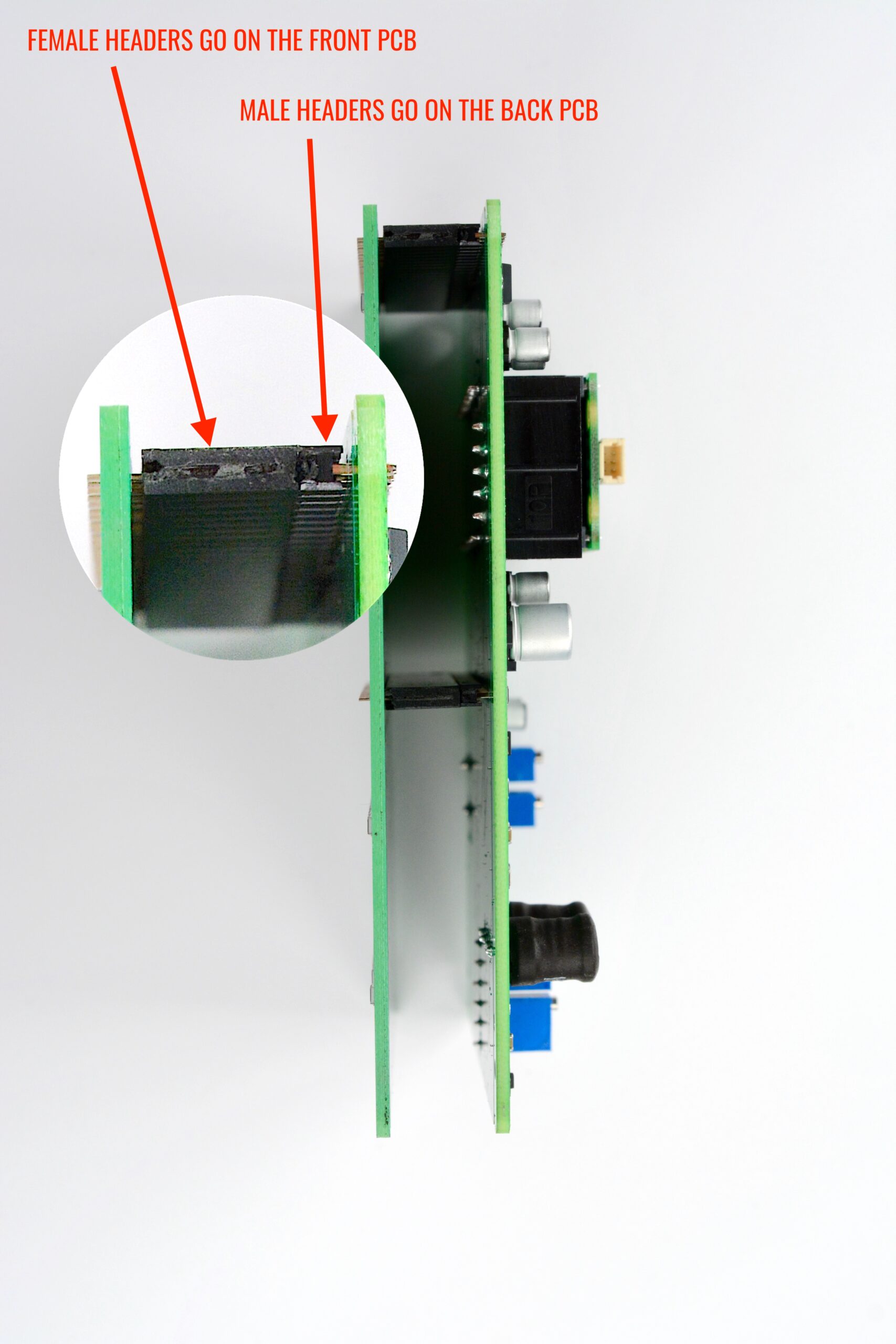
7. Soldering the PCB interconnect headers.
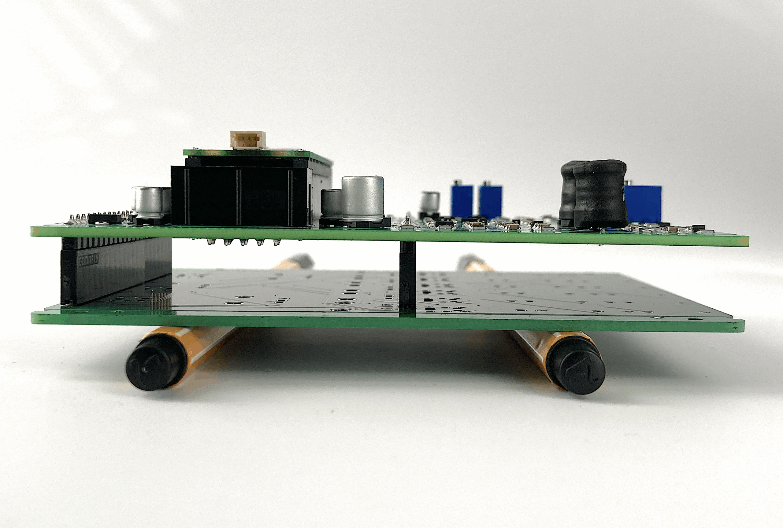
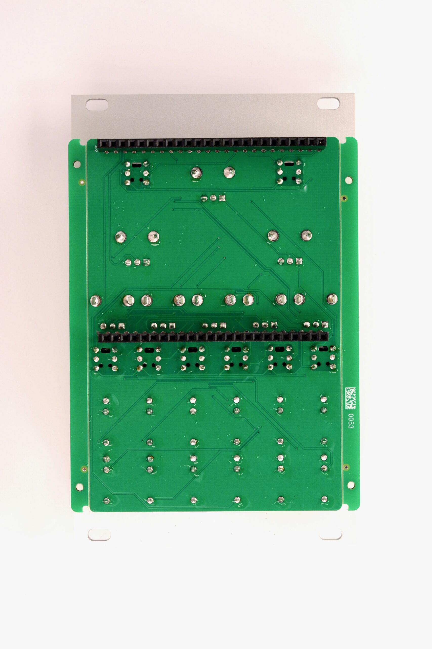
Now it’s time to solder the 24 pin male PCB interconnect headers to the back PCB. The image above illustrates the orientation of the header assembly we made in the last step. The male headers must face towards the back PCB (the one with all the components) and the female headers must face towards the front PCB. The best way to solder the 24 pin headers is to place the front PCB front side down on a flat surface with something under it to get off the surface of the table, for example a couple of pens. Make sure the two 24 pin sockets on the PCB are not obstructed by whatever is under the PCB.
Now place the two header assemblies on the front PCB with the female headers down towards the front PCB. Make sure everything is aligned and straight. See image for reference.With everything aligned, carefully solder the first and last pins of both headers to stabilize everything. Then check that the headers are straight and flush with the PCB. If not, make the necessary adjustments. When everything is good, solder the rest of the pins.
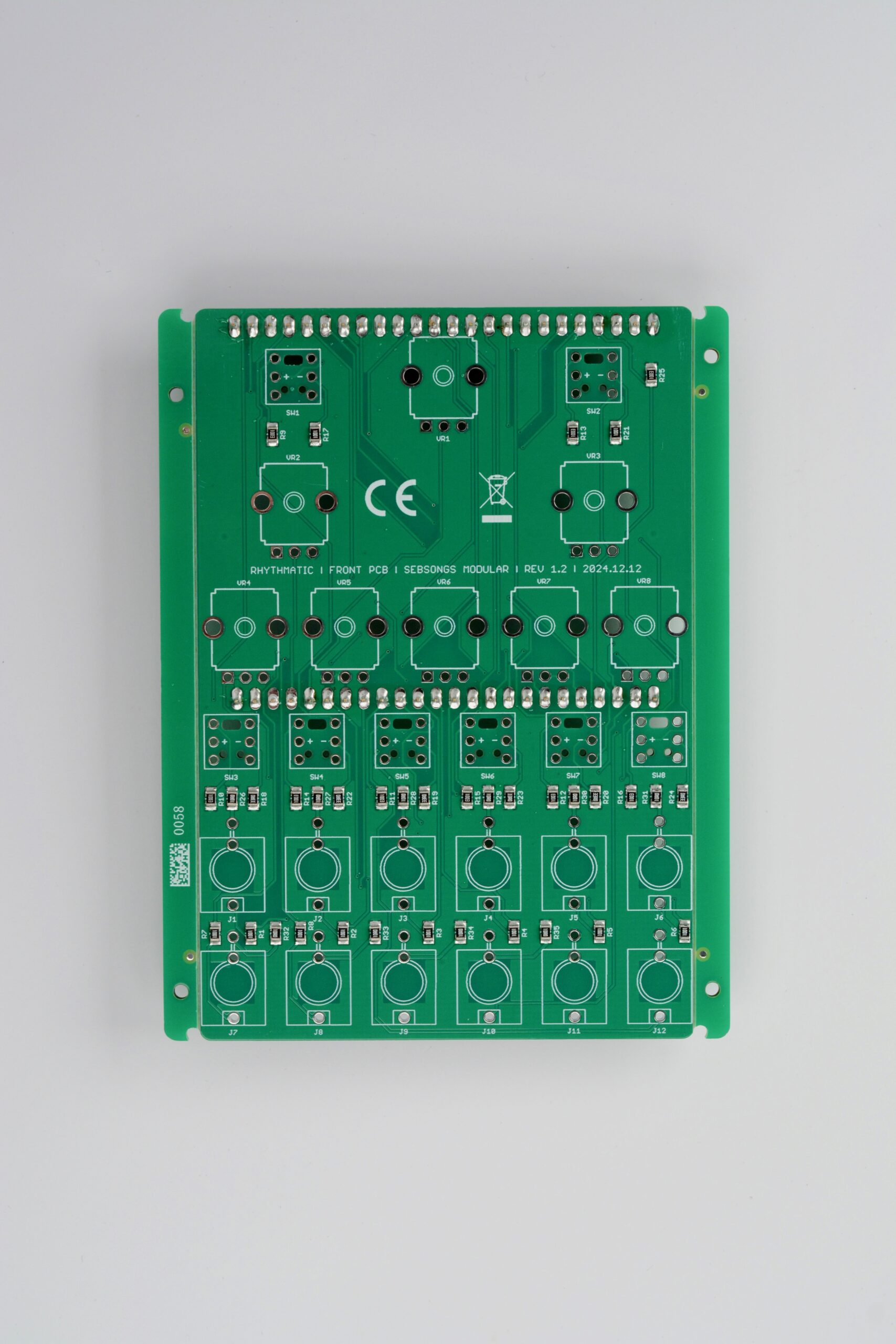
FRONT PCB
8. Headers
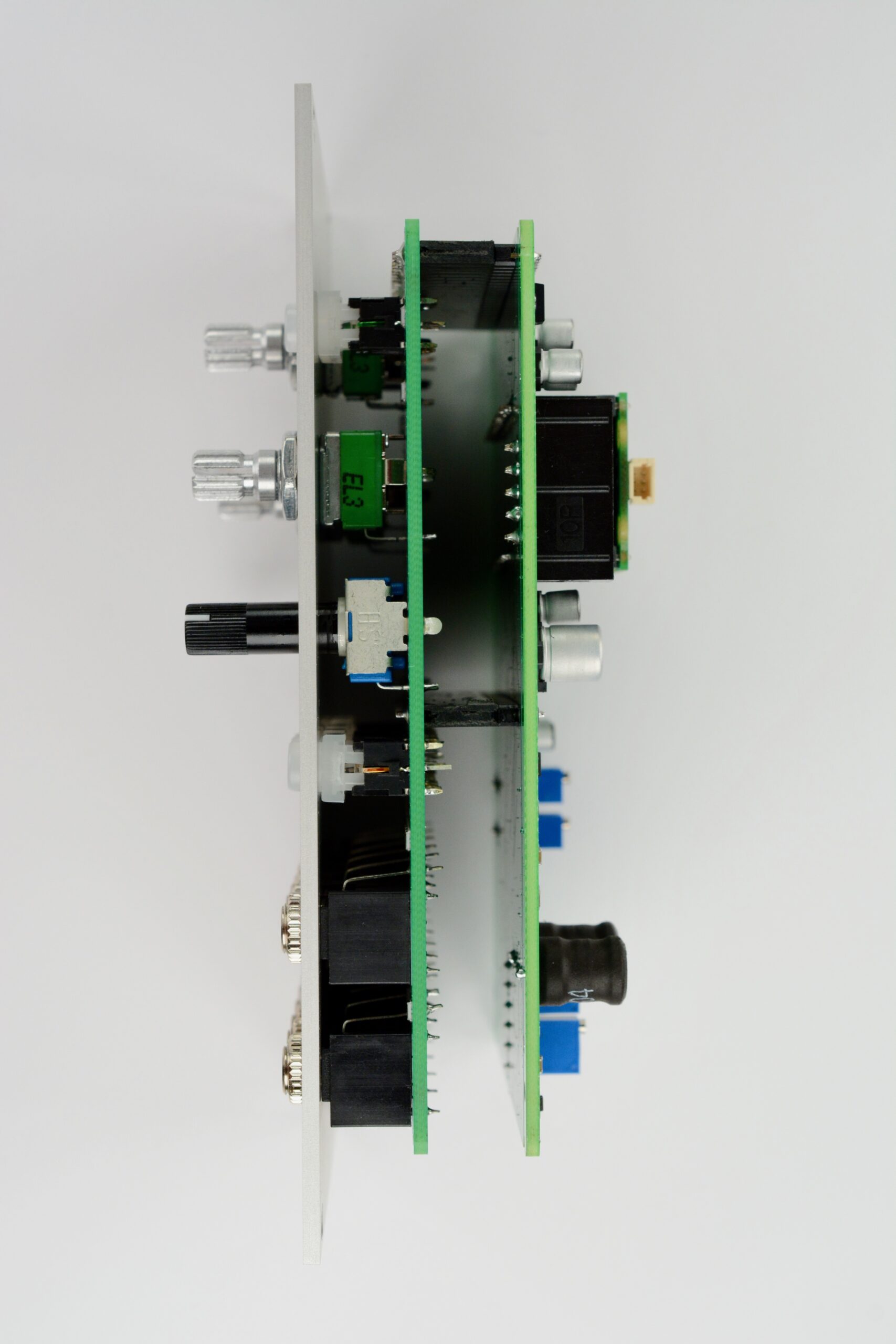
Fit the front PCB to the 24-pin female headers that are still mounted on the male headers of the back PCB. Make sure the front side of the PCB is facing up. Double check that the two PCBs align with each other and that the front side of the front PCB is facing up, see image for reference. Then solder the headers. Finally, pull the front and back PCBs apart and store the back PCB safely for final assembly later on.
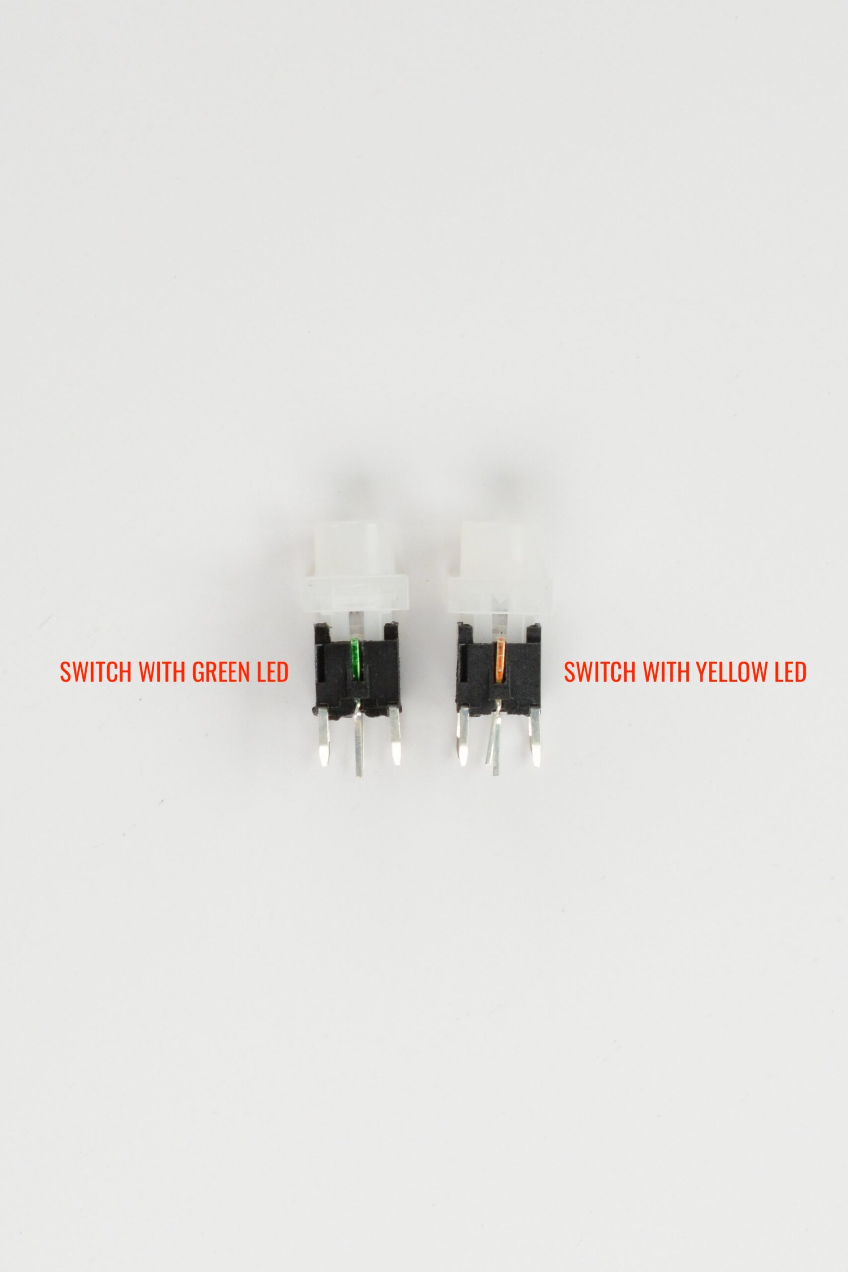
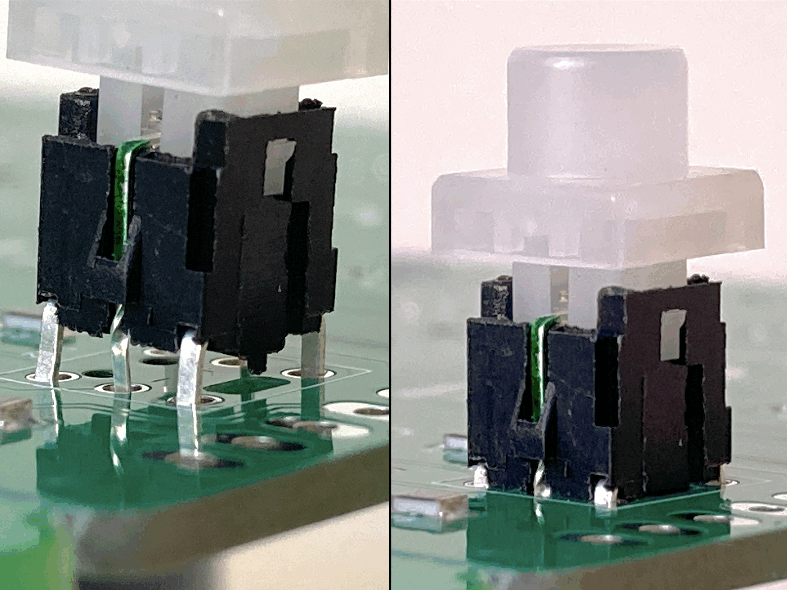
4. Panel components
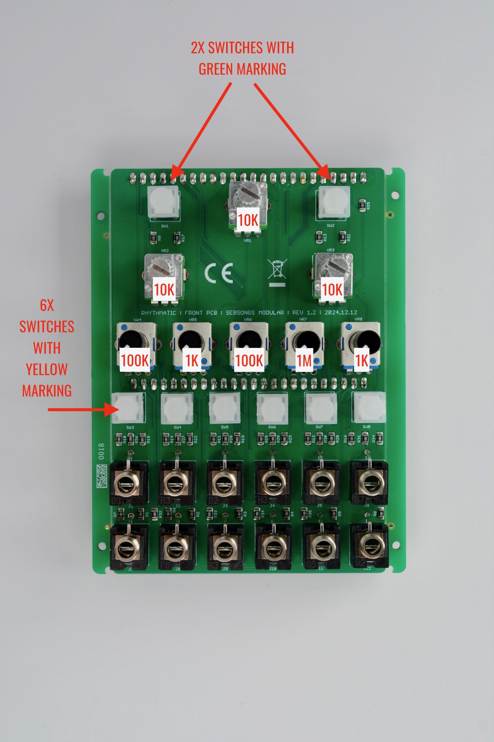
Identify and double check that you have 2x switches with GREEN LED and 6x switches with YELLOW LED.When placing the switches, make sure that the tabs on the bottom of the switches align with the holes in the PCB. When fully seated, the bottom of the switches should be flush with the PCB without any air gap. See images for reference. Place all panel components in their corresponding holes on the PCB as shown in the image above. Make sure that the GREEN switches are place on the SW1 and SW2 positions and the YELLOW switches are in the SW3 through 8 positions.
Be very careful to place the correct value potentiometers in the correct position: VR1, VR2, VR3: B10K Alpha potentiometers. VR4, VR6: B100K Tall trimmer potentiometers. VR5, VR8: B1K Tall trimmer potentiometers. VR7: B1M Tall trimmer potentiometer.
DO NOT SOLDER ANYTHING YET!Place the front panel over the jacks, potentiometers and switches and fit all the nuts and washers. Hand tighten all nuts lightly to keep the panel in place.
Make sure the 5 tall trimmer potentiometers are properly centered in the panel holes. It can be a little bit fiddly to get them perfect, but it’s worth the effort.Flip the whole assembly, make sure that everything is nice and straight. Then solder all the solder joints. If you can, lightly push the switches in while soldering them to make sure they are soldered flush to the PCB.
5. Finishing up
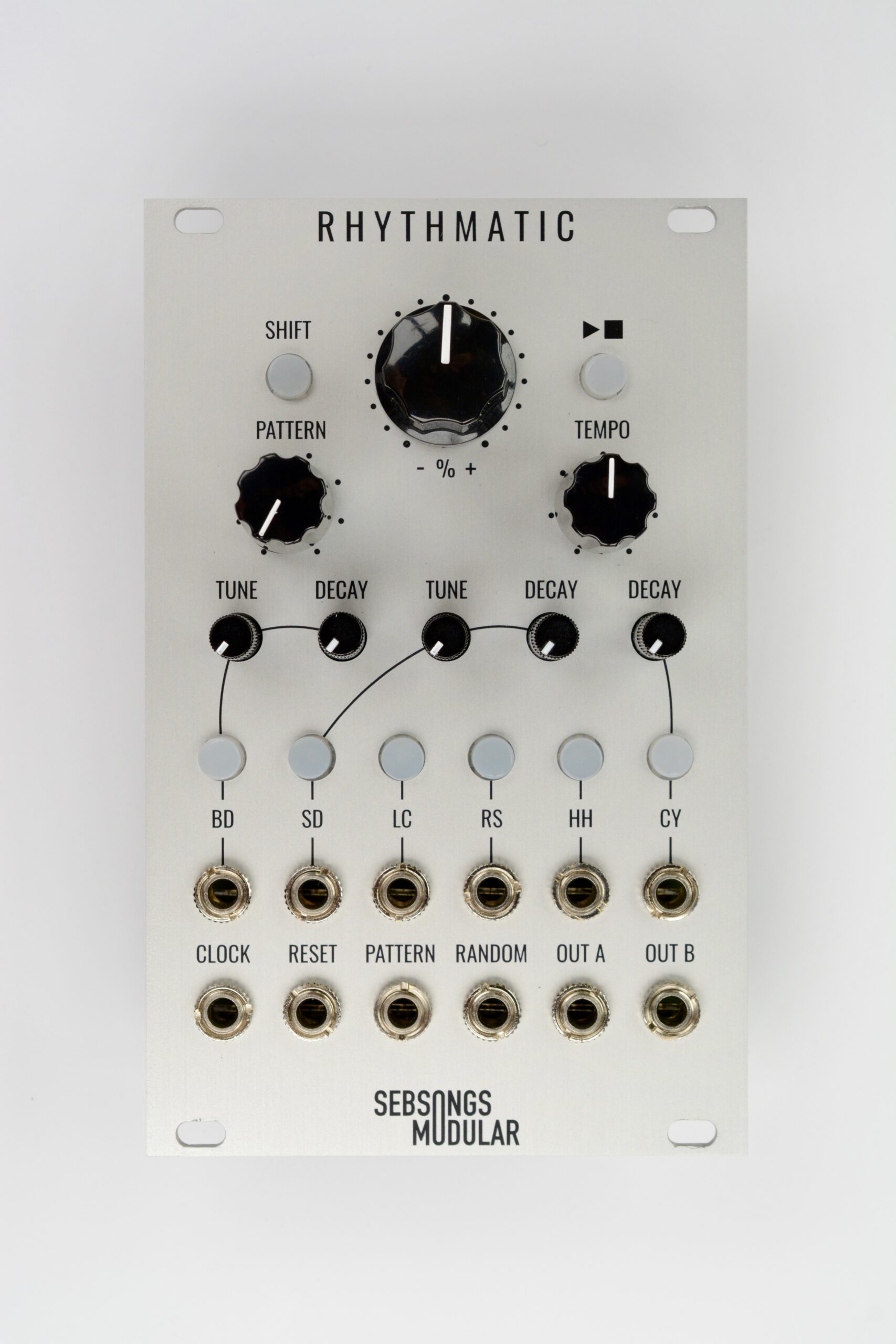
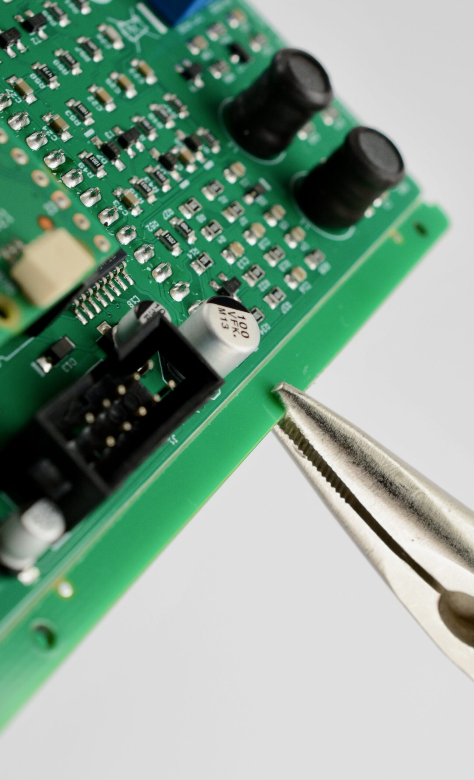
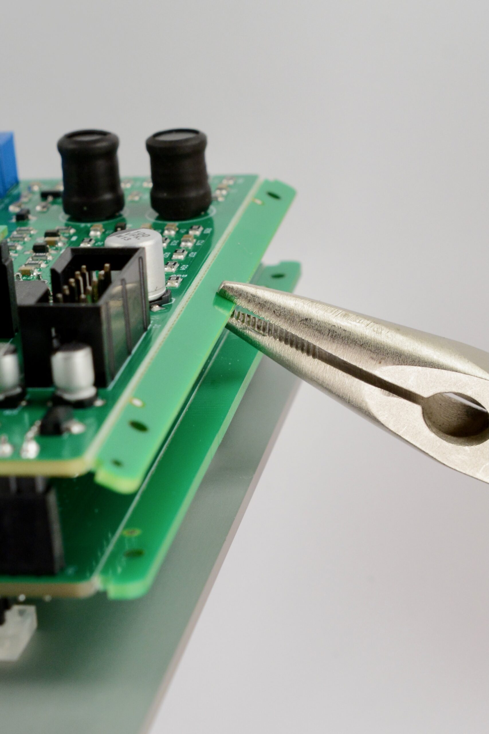
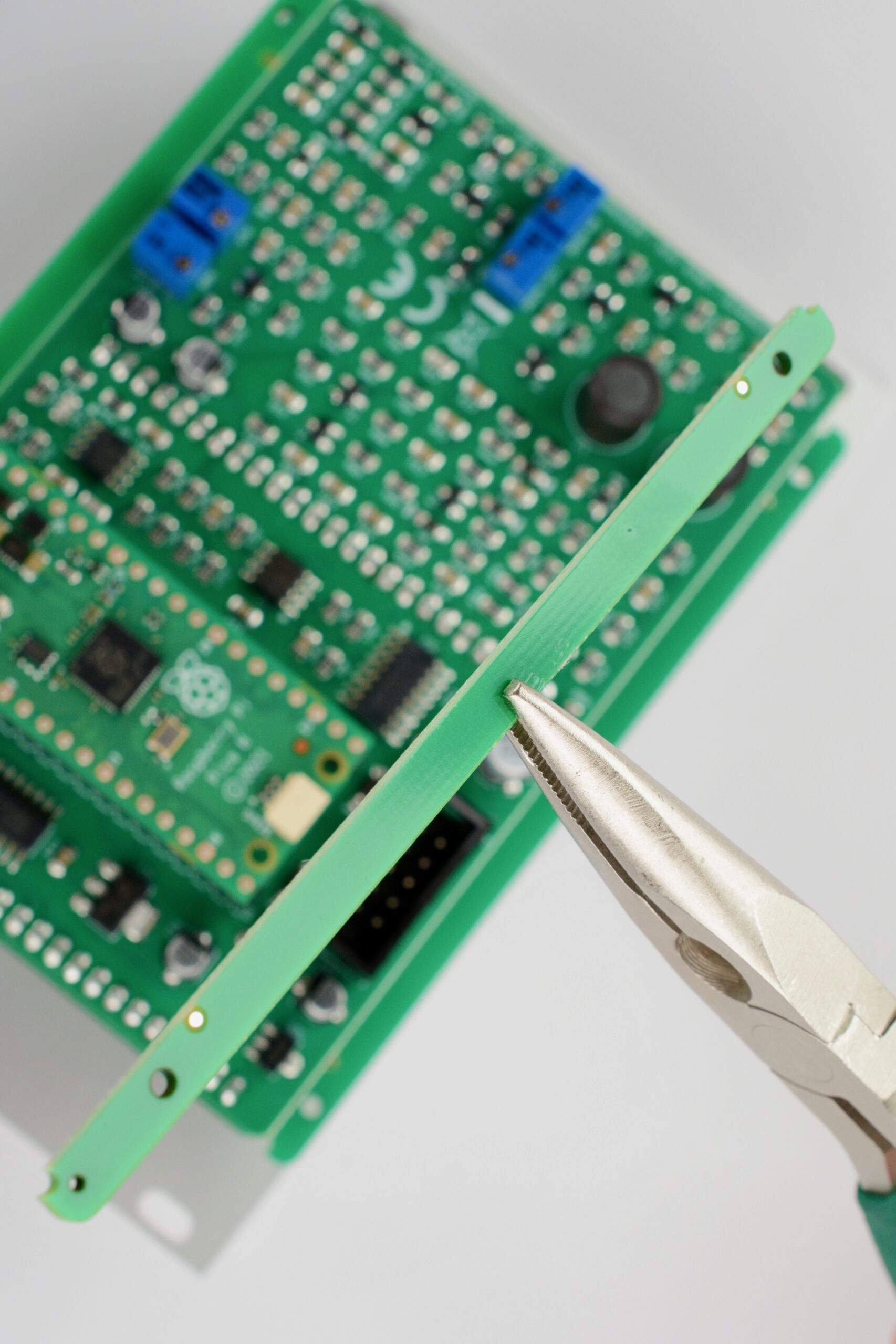
Now you can fit the back PCB to the front PCB and panel assemply.Tighten all nuts with appropriate tools and fit the knobs on the top potentiometers.Finally, break off the tabs from the edges of the PCB. These are from the PCB manufacturing and they are convenient in the assembly process, but we don’t need them anymore! Get a pair of snipe or flat nose pliers and grip the PCB tabs one at a time. Carefully break off the tabs in an up and down motion. The tabs come off easily, but take care not to damage anything else on the module.This is what the tabs look like when they are broken off. Proceed to break off all four tabs. When all tabs have been broken off, the module is finished!
6. Powering up and testing
Before powering on, measure resistance with a multimeter between ground and + and – respectively on the power connector to make sure there are no short circuits. The resistance should be in the 100K-1M ohms range for the positive side and 5-10K ohms for the negative side.
At first power on, the factory presets have not been loaded into the pattern and bank memory. The firmware should notice this automatically and load all factory settings at start up. However, if it for some reason doesn’t do that you can do this manually.
To restore the factory patterns and reset all settings to their default states, please follow this procedure:
Power OFF the module.
Press and hold the SHIFT and PLAY/STOP buttons.
Continue to hold the buttons pressed down as the module is powered back ON.
The drum channel LEDs will animate as a progress bar going from left to right.
When the LED animation has stopped, let go of the buttons. Factory reset has been successful.
It is also a good idea to calibrate the ranges of the Pattern and Random knobs:
Power OFF the module.
Turn the pattern and random knobs all the way counter clockwise, i.e. to their minimum positions.
Press and hold the SHIFT button.
Continue to hold the SHIFT button pressed down as the module is powered back ON.
The drum channel LEDs will light up from both sides animating in towards the middle.
When the LED animation has stopped, let go of the SHIFT button. The pattern and random knobs are now calibrated.