
ATTENUVERT x6 | BUILD INSTRUCTIONS
Preparations
This build is a beginner level build, but with a few surface mount components. However, this is a good project to get into surface mount components, and an otherwise simple build.
Do this before building this module:
- Check that you have all components.
- Gather all the tools needed (see lists below).
The tools needed for this build are:
- Soldering station or soldering iron.
- High quality solder (lead free recommended).
- Fine tipped side cutters.
- Round-nosed pliers (for bending component legs).
- Angled tweezers for surface mounting.
Recommended accessories:
- PCB holder (makes life much easier).
- Breadboard.
- Knurled Nut Driver Tool (for tightening jack socket nuts).
Got everything? Let’s get on with it!
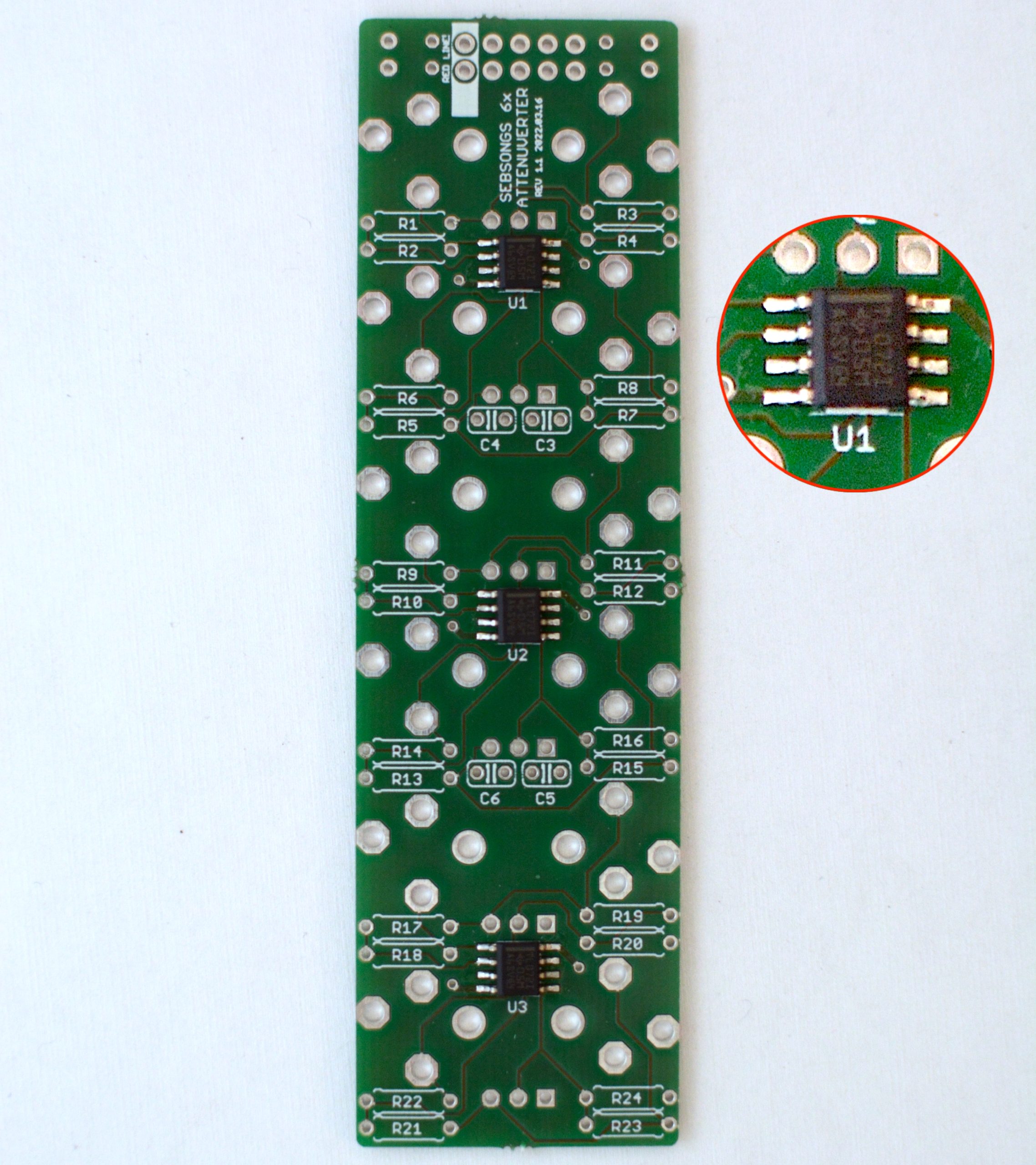
1. ICs
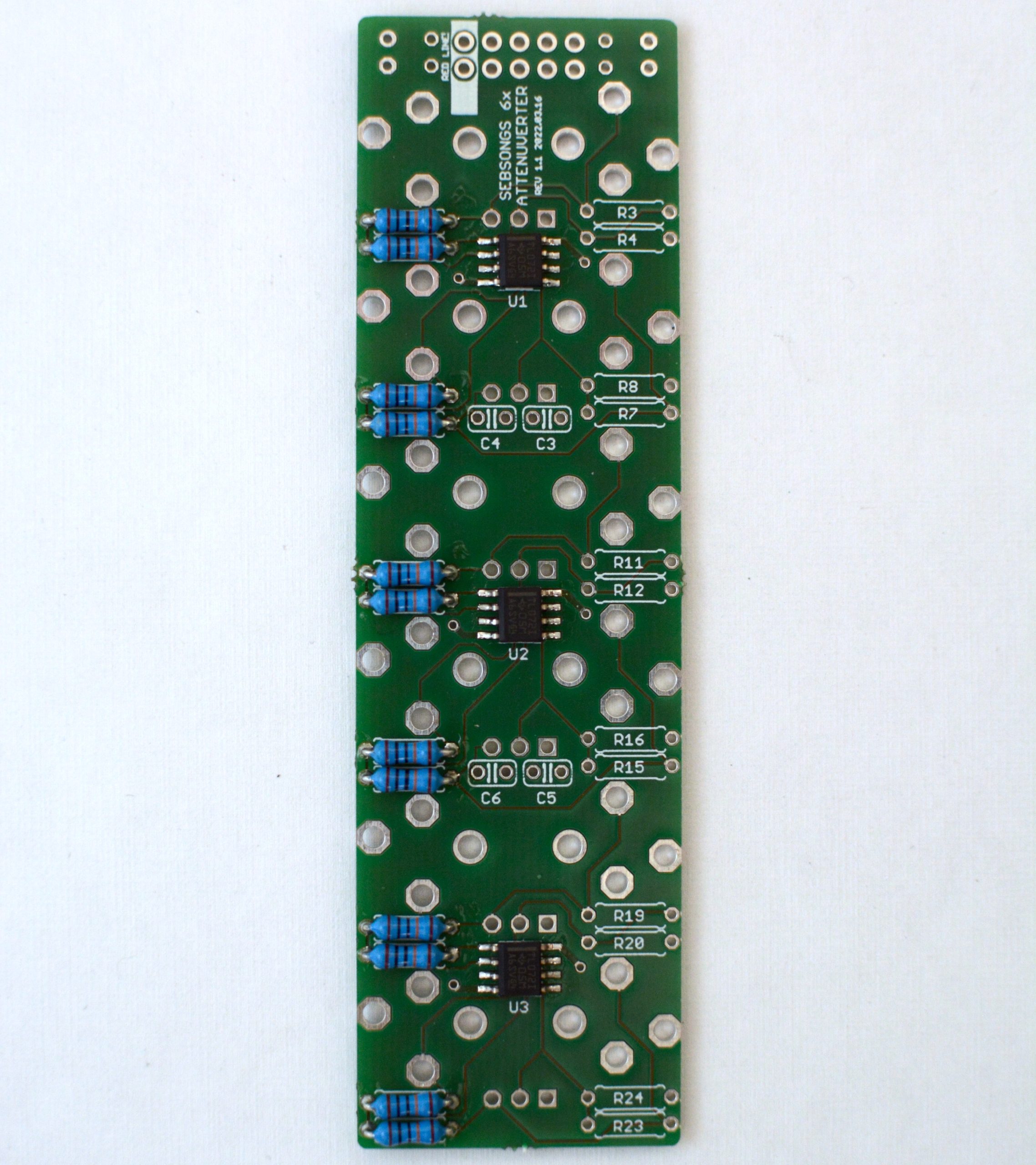
2. Resistors

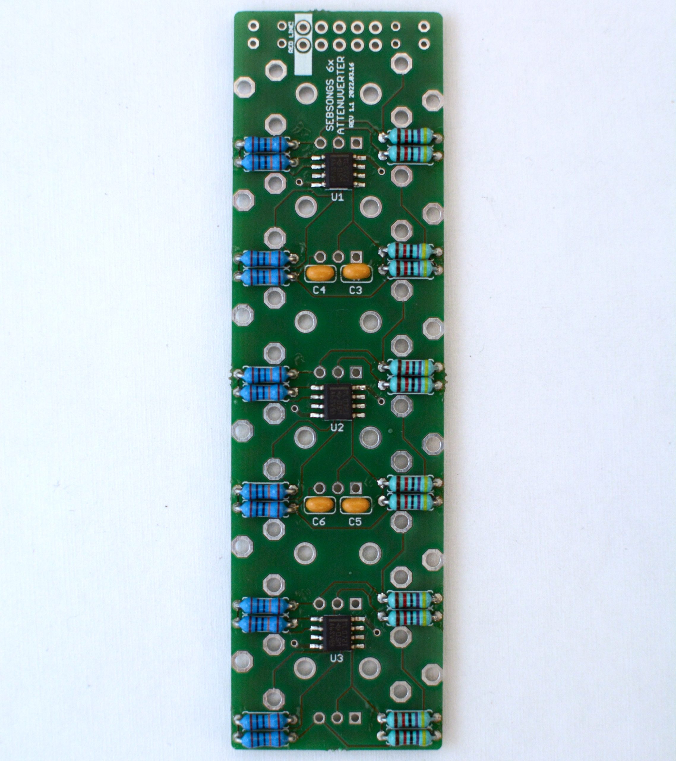
2. Capacitors

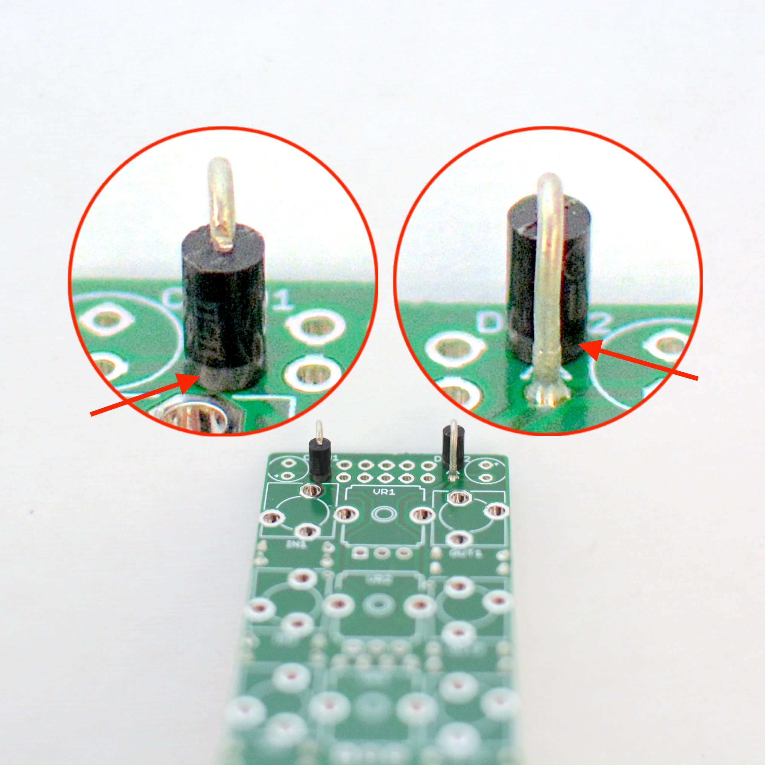
3. Diodes
4. Headers

5. Jacks sockets and potentiometers
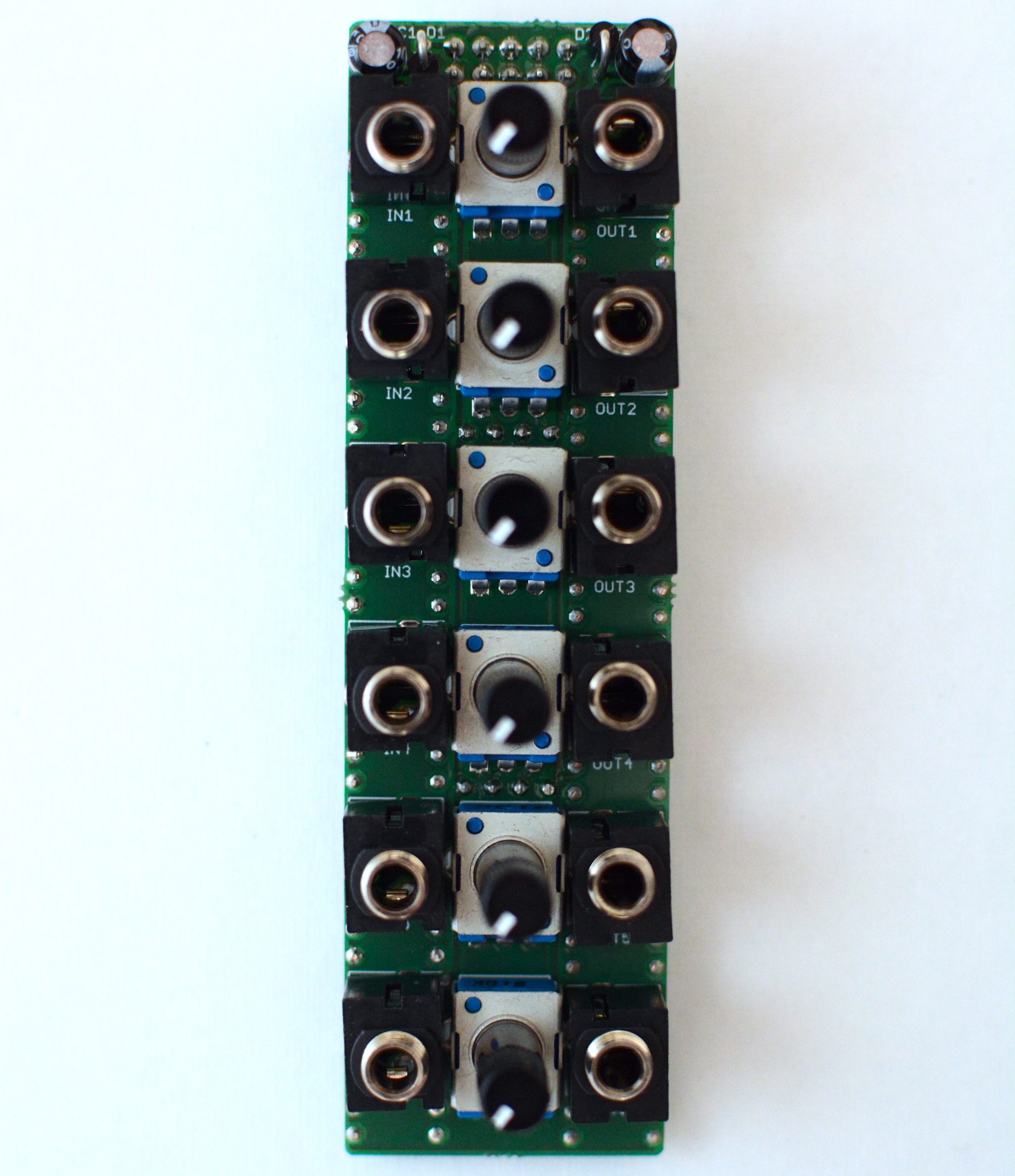
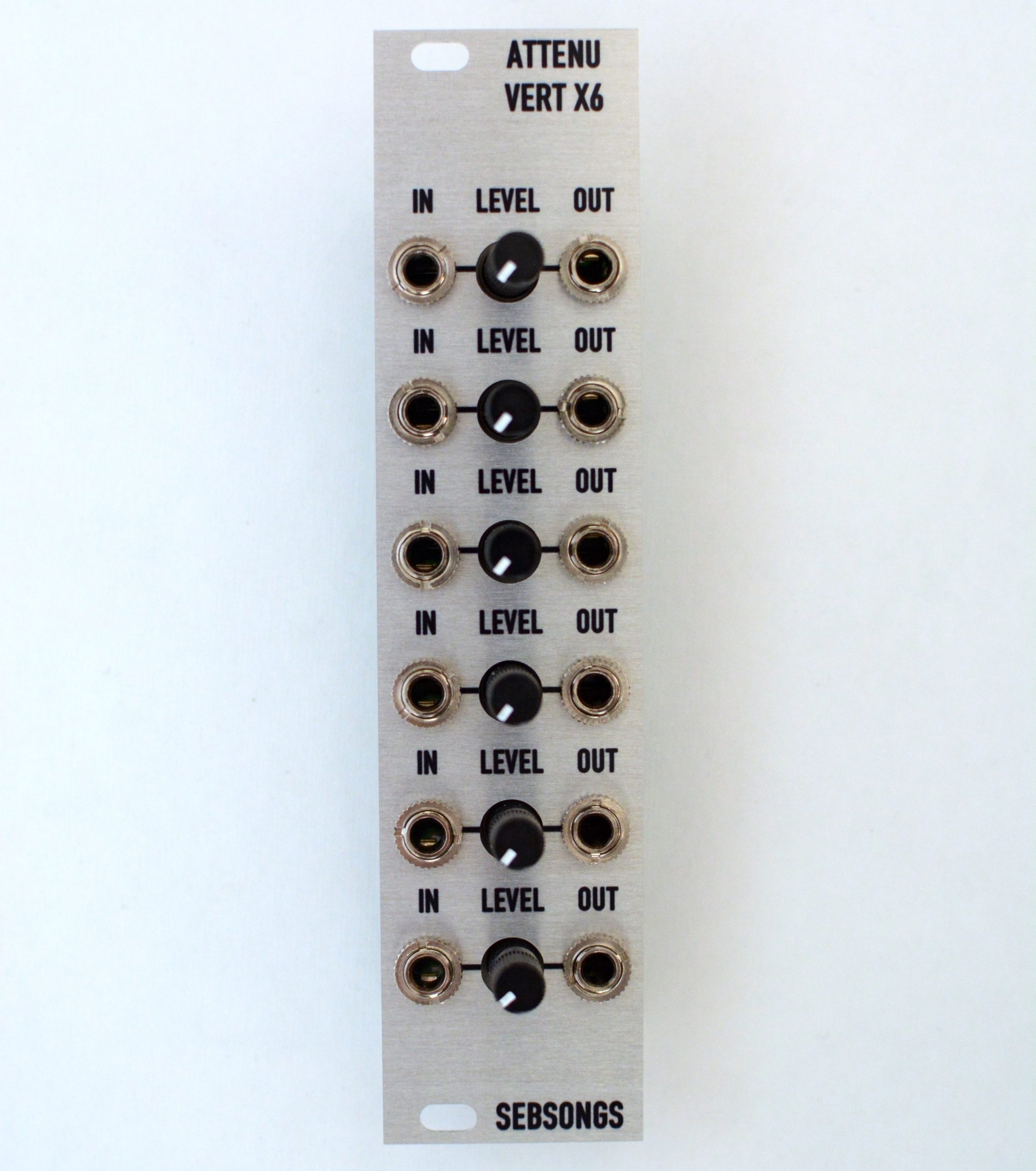
6. Powering up and testing
Connect a 10-pin eurorack power cable to the power socket and attach the module in your eurorack case. Connect a signal to one of the inputs (for instance a sawtooth wave from an LFO) and feed the corresponding output to a module (for instance the FM input on a VCO). Set the potentiometer to 12 o’clock. There should be no signal going through the attenuverter. Increase the level and there should now be a sawtooth signal going through. Decrease the level and there should be an inverted sawtooth (ramp) going through the attenuverter.