This build is an intermediate level build, not recommended for absolute beginners. If you are a beginner, it is recommended that you build something simpler before starting this project.
Note that the development board (Arduino Nano) used in this module comes pre-programmed when purchased from Thonk.
Do this before building this module:
Check that you have all components.
Gather all the tools needed (see lists below).
The tools needed for this build are:
Soldering station or soldering iron.
High quality solder (lead free recommended).
Fine tipped side cutters.
Round-nosed pliers (for bending component legs).
Masking tape.
Calipers or similar measuring tool.
Recommended accessories:
PCB holder (makes life much easier).
Breadboard.
A fine grade file (for finishing off cut header edges).
10 mm hex socket covered in masking tape (for tightening nuts).
Knurled Nut Driver Tool (for tightening jack socket nuts).
Got everything? Let’s get on with it!
1. Resistors
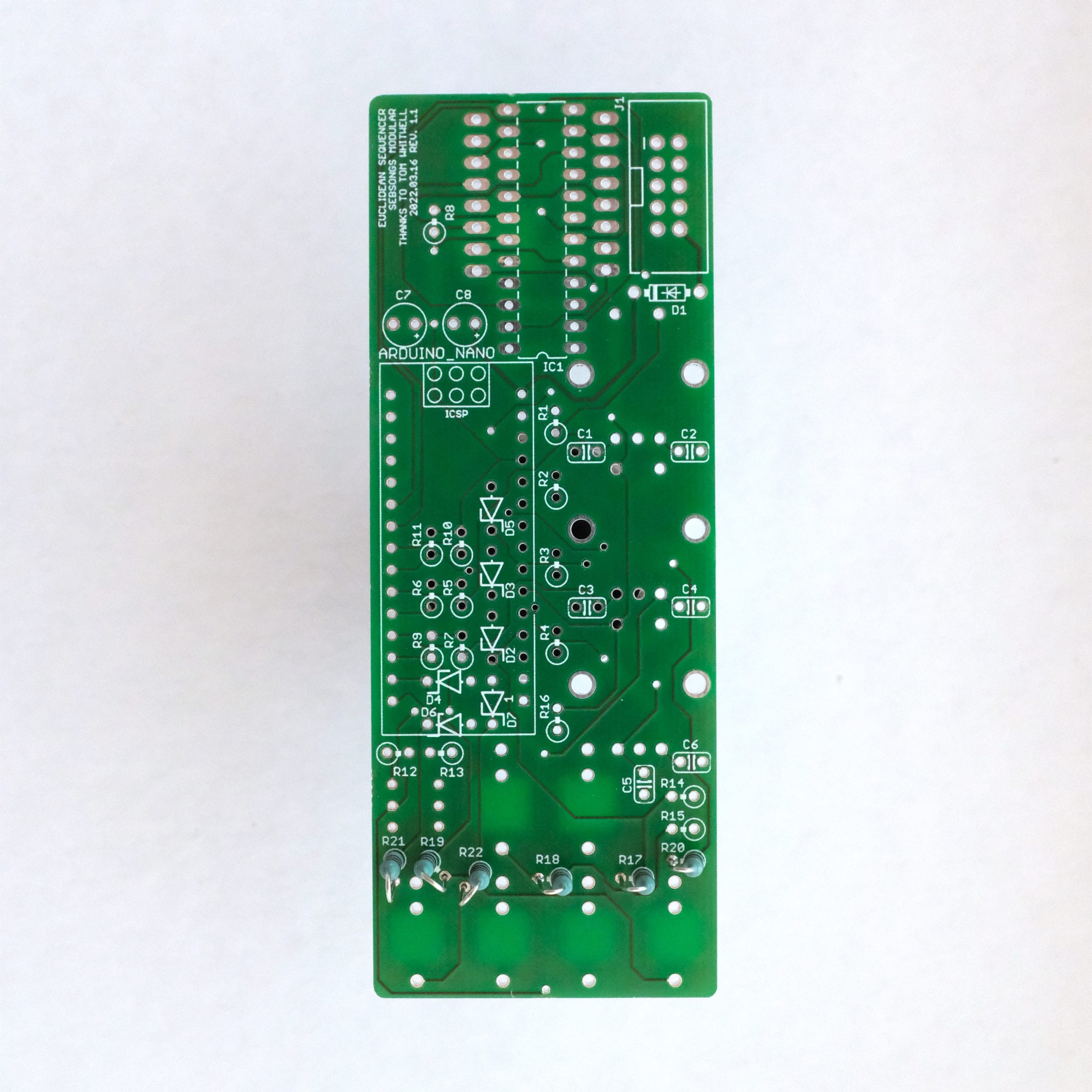
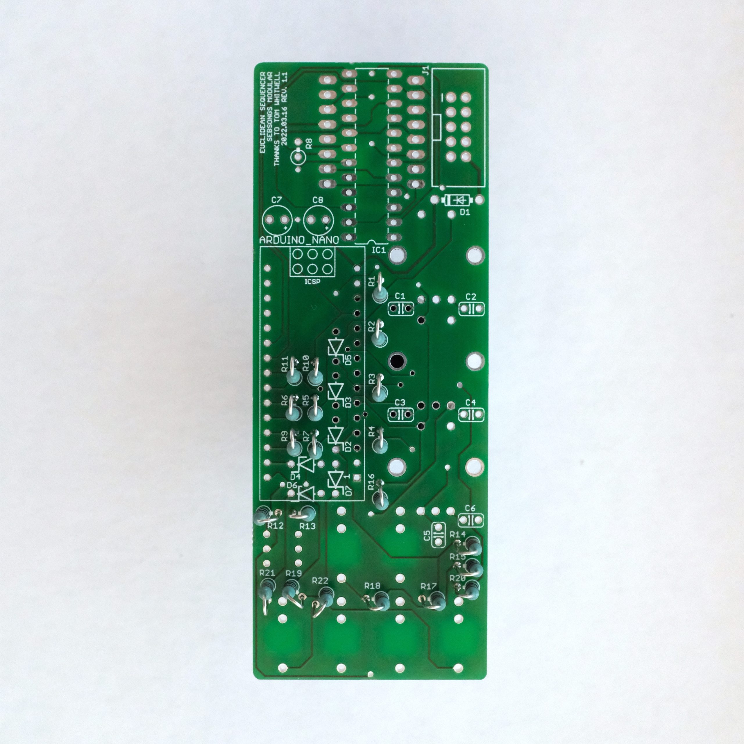
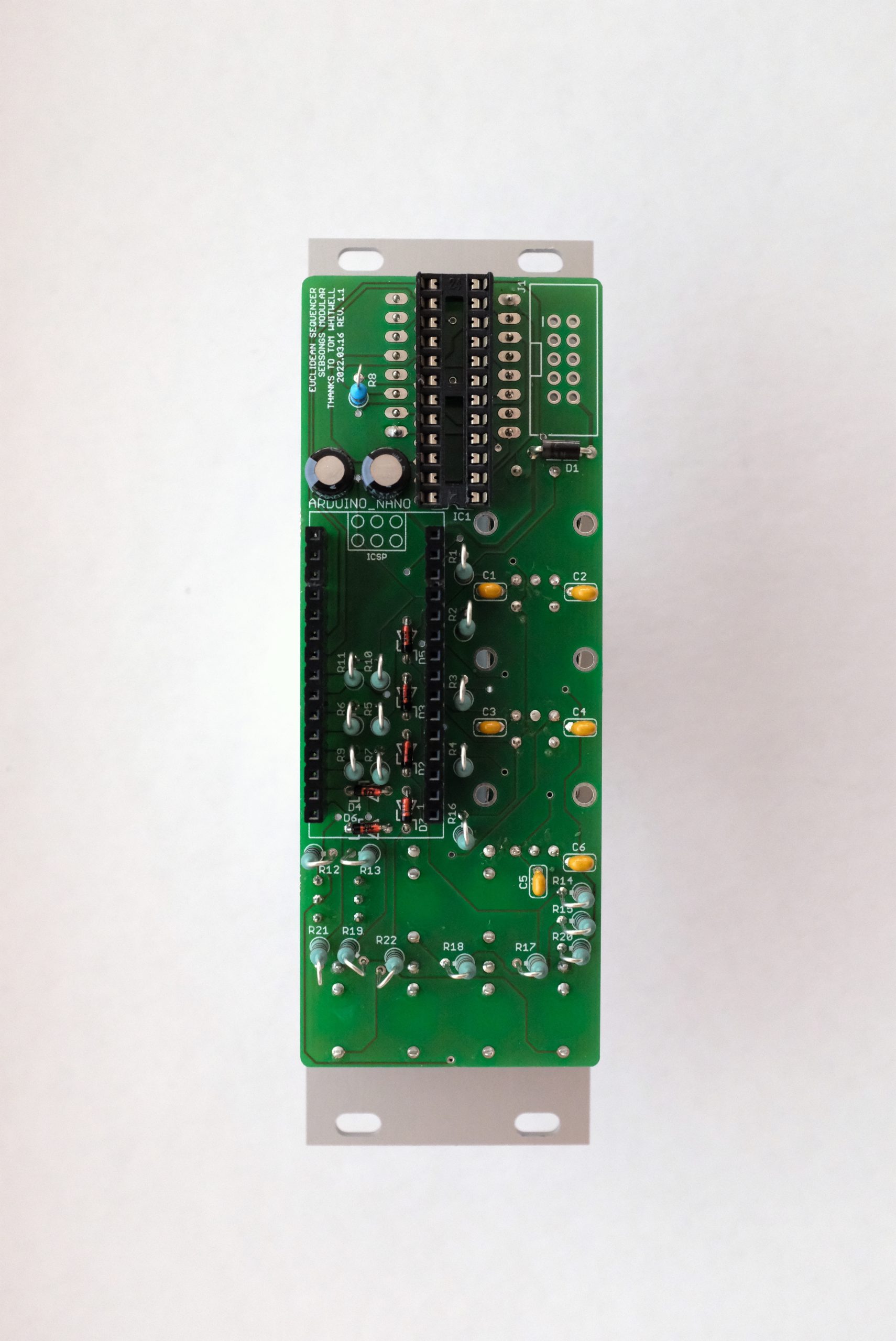
Solder all 1K resistors (R17, R18, R19, R20, R21, R22). Bend one leg on each resistor in order to prepare them for standing assembly.
Solder all 10K resistors (R1, R2, R3, R4, R5, R6, R7, R9, R10, R11, R12, R13, R14, R15, R16). Bend one leg on each resistor in order to prepare them for standing assembly.Solder the 20K resistor (R8). Bend one leg on the resistor in order to prepare it for standing assembly.
2. Capacitors
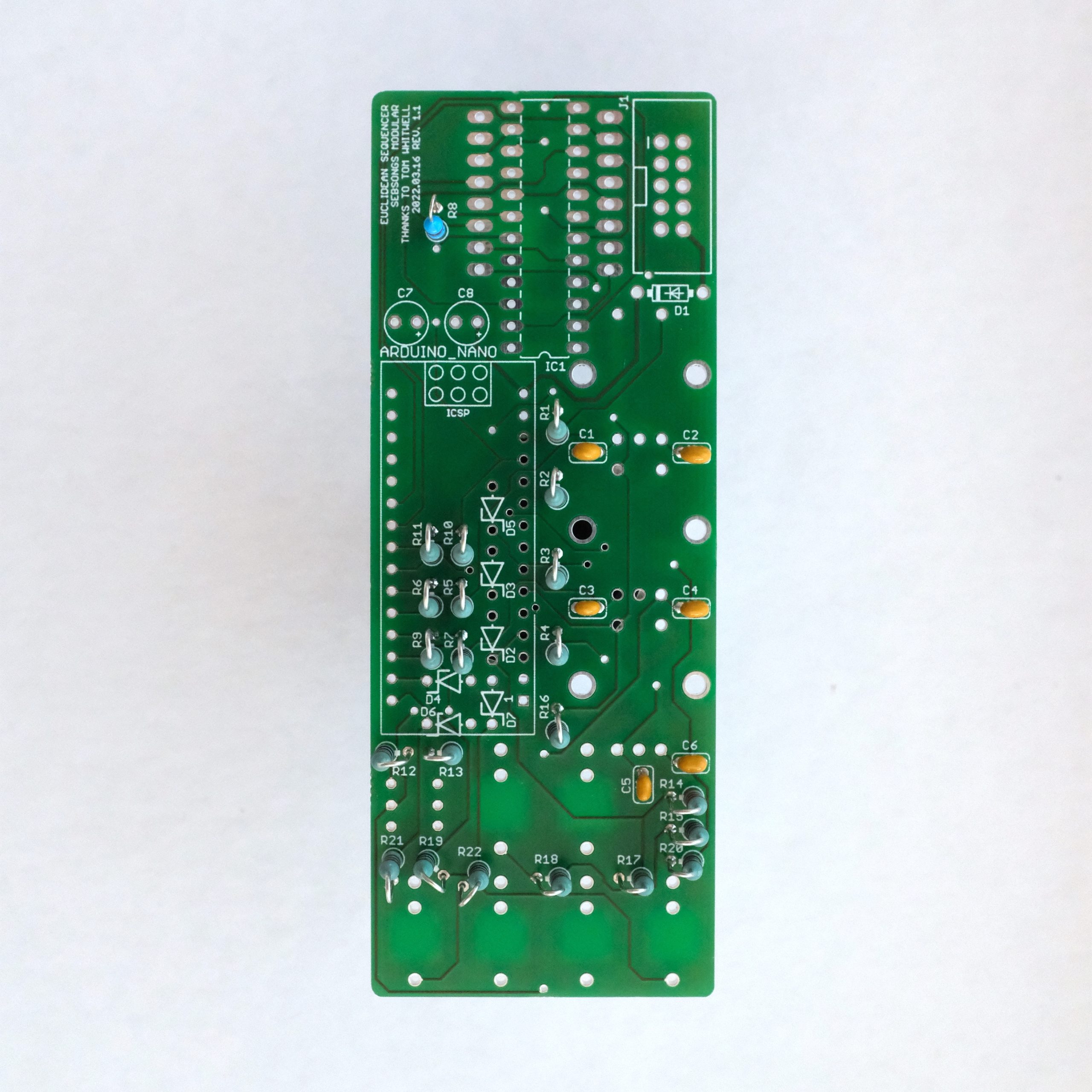
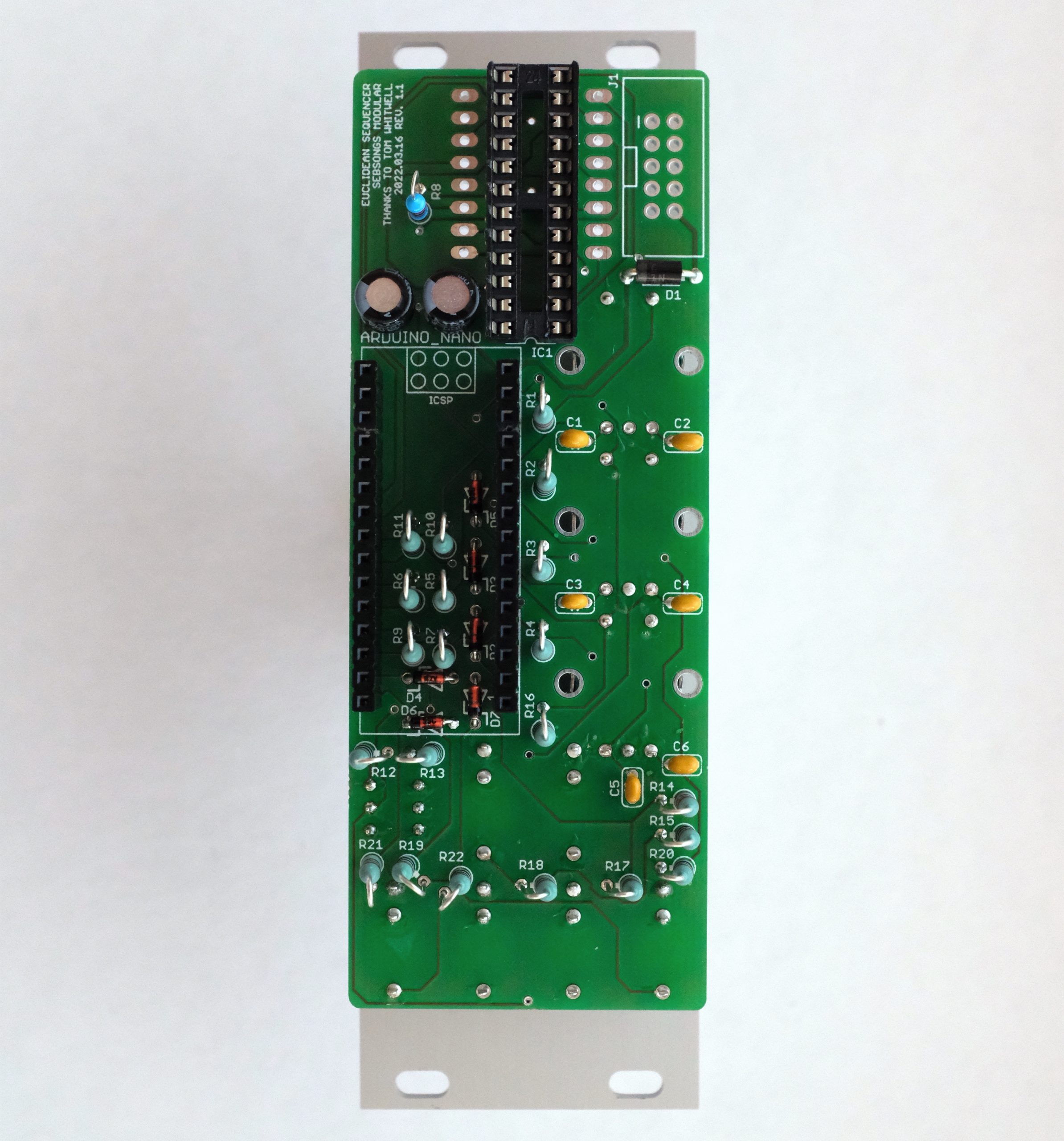
Solder the 100nF ceramic capacitors (C1, C2, C3, C4, C5, C6). Solder the 22uF electrolytic capacitors (C7, C8). Make sure to check the polarity twice before soldering, the long leg must go to the hole with the plus symbol!. See image for reference.
3. Diodes
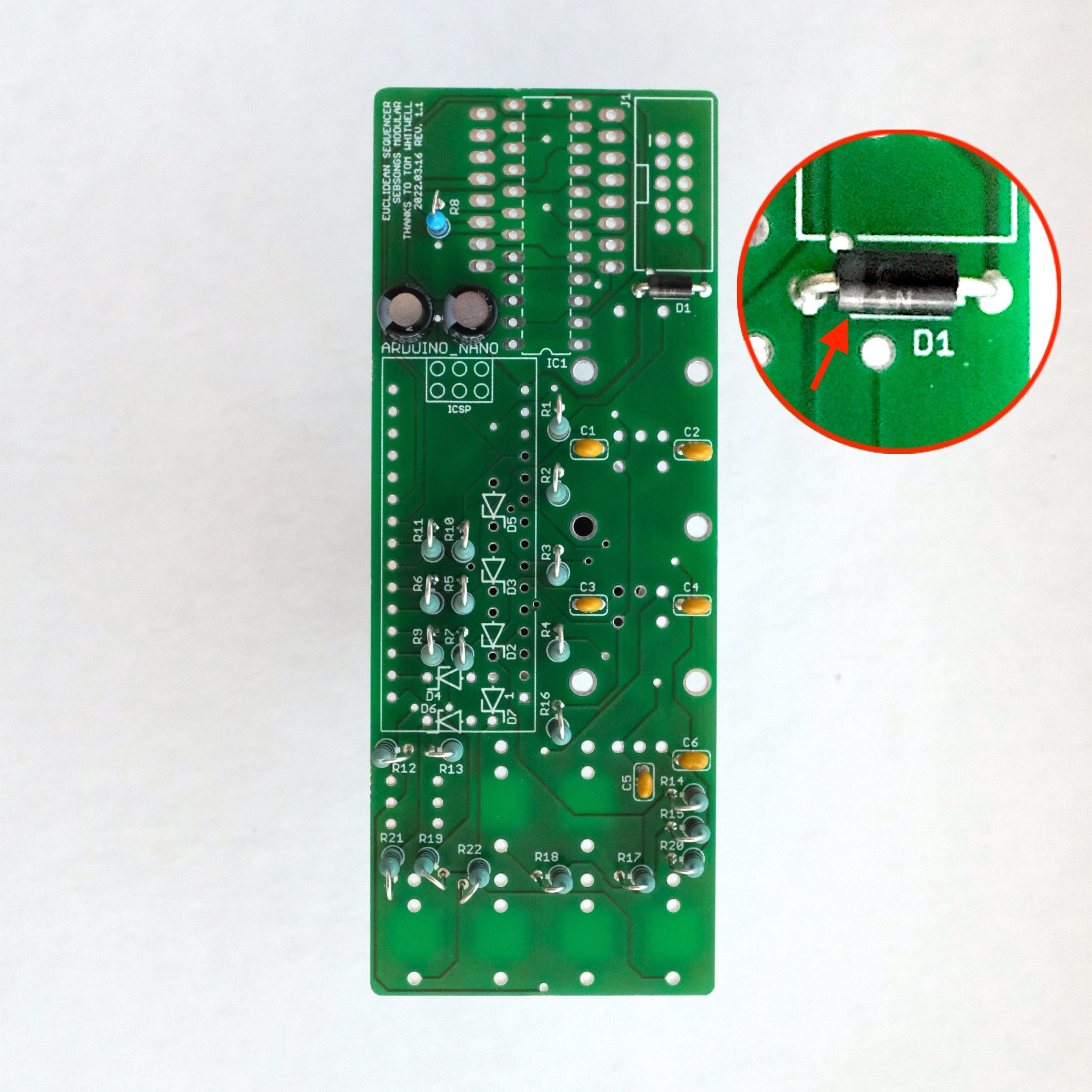
Solder the 1N5819 schottky diode (D1). Make sure to check the polarity twice before soldering. See image for reference.Solder the BZX55C5V1 zener diodes (D2, D3, D4, D5, D6, D7). Make sure to check the polarity twice before soldering. See image for reference.
4. Sockets and headers
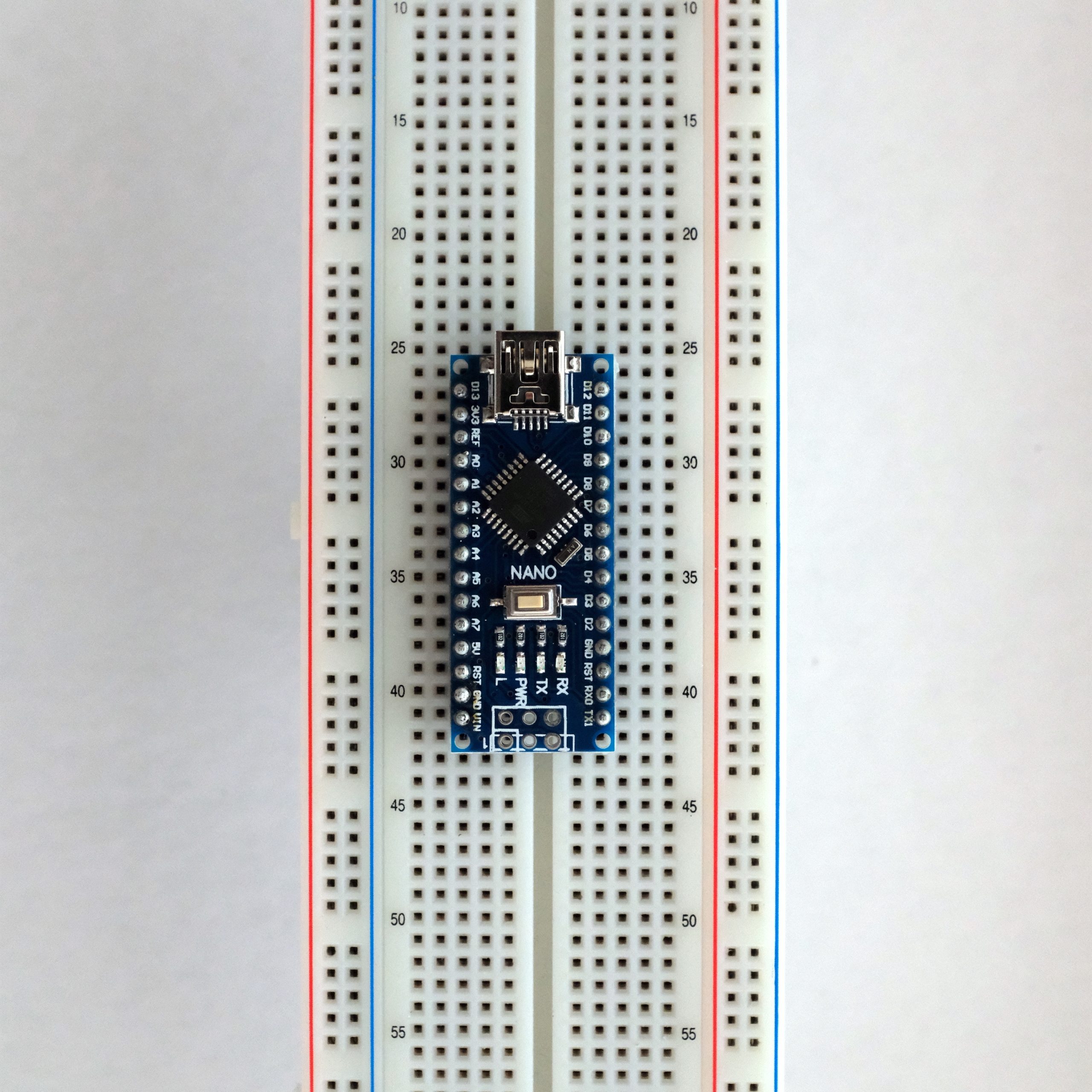
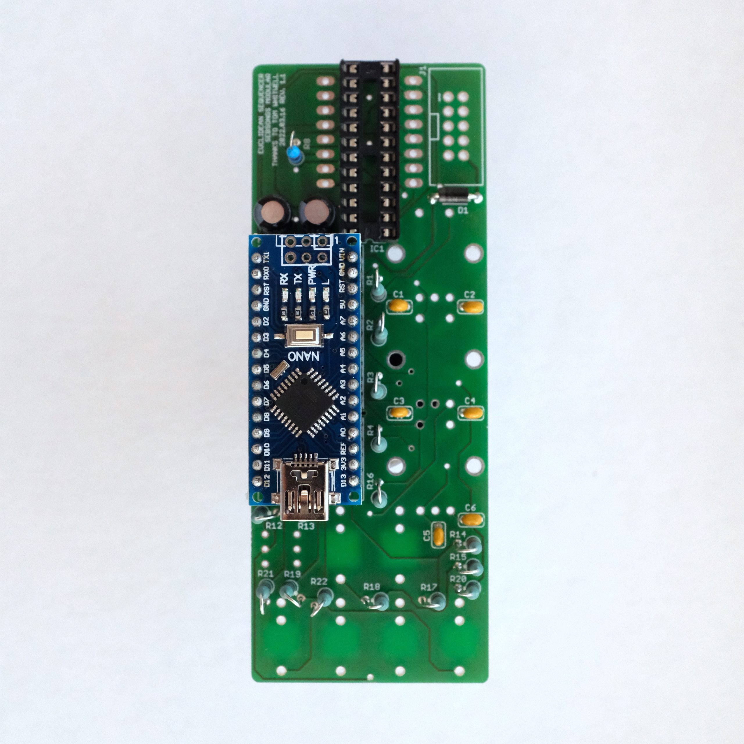
Solder the 24 pin IC socket for the IC1. Make sure the notch lines up with the silk screen on the PCB. See image for reference.Solder the pin headers on the Arduino Nano, ideally using a breadboard as shown in the picture.Press the female headers on to the Arduino Nano pins in order to prepare for soldering the headers on to the PCB.With the Arduino still mounted to the female headers, solder the female headers to the PCB. Remove the Arduino Nano to find the female headers firmly soldered to the PCB.
5. Switch, jacks sockets and encoders
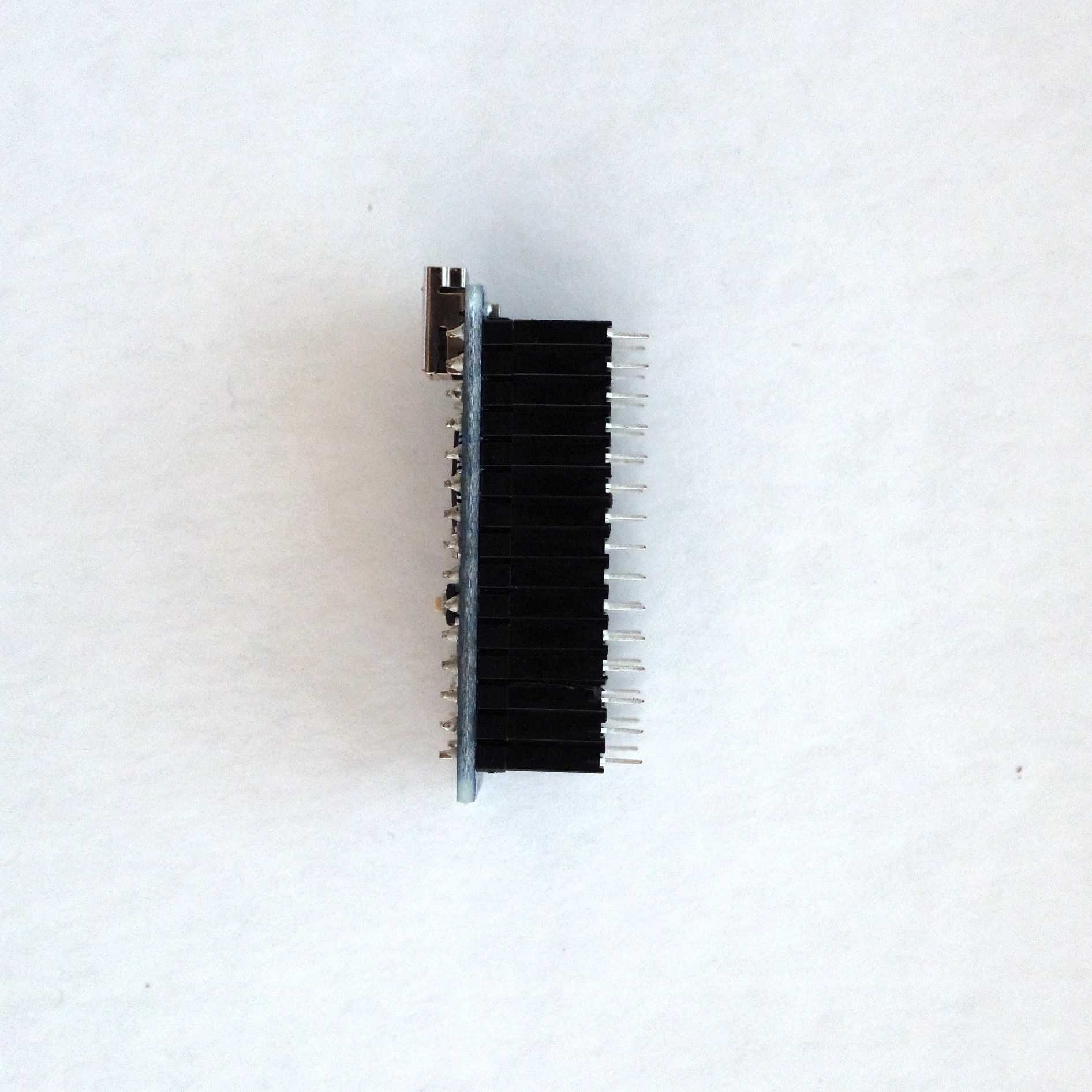
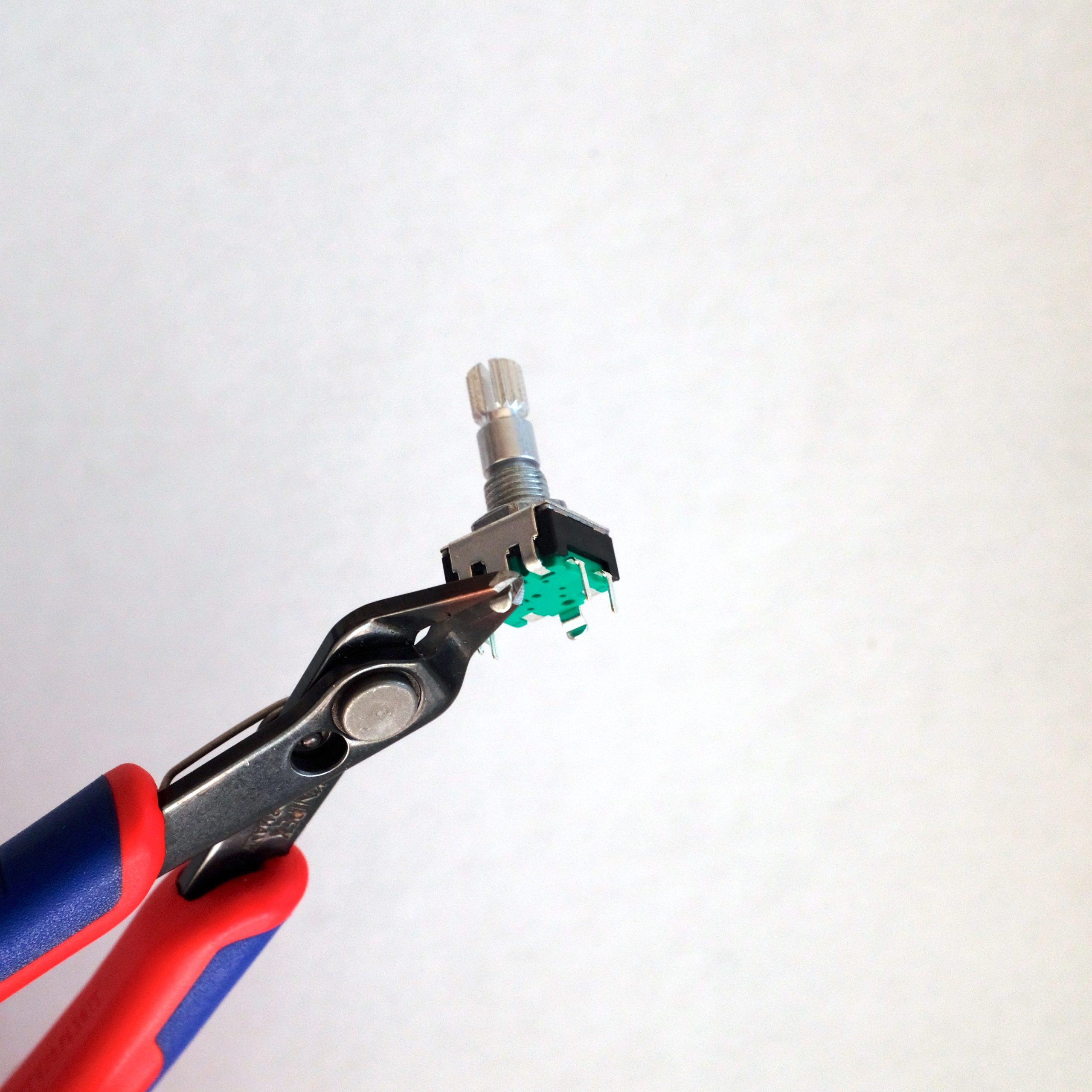
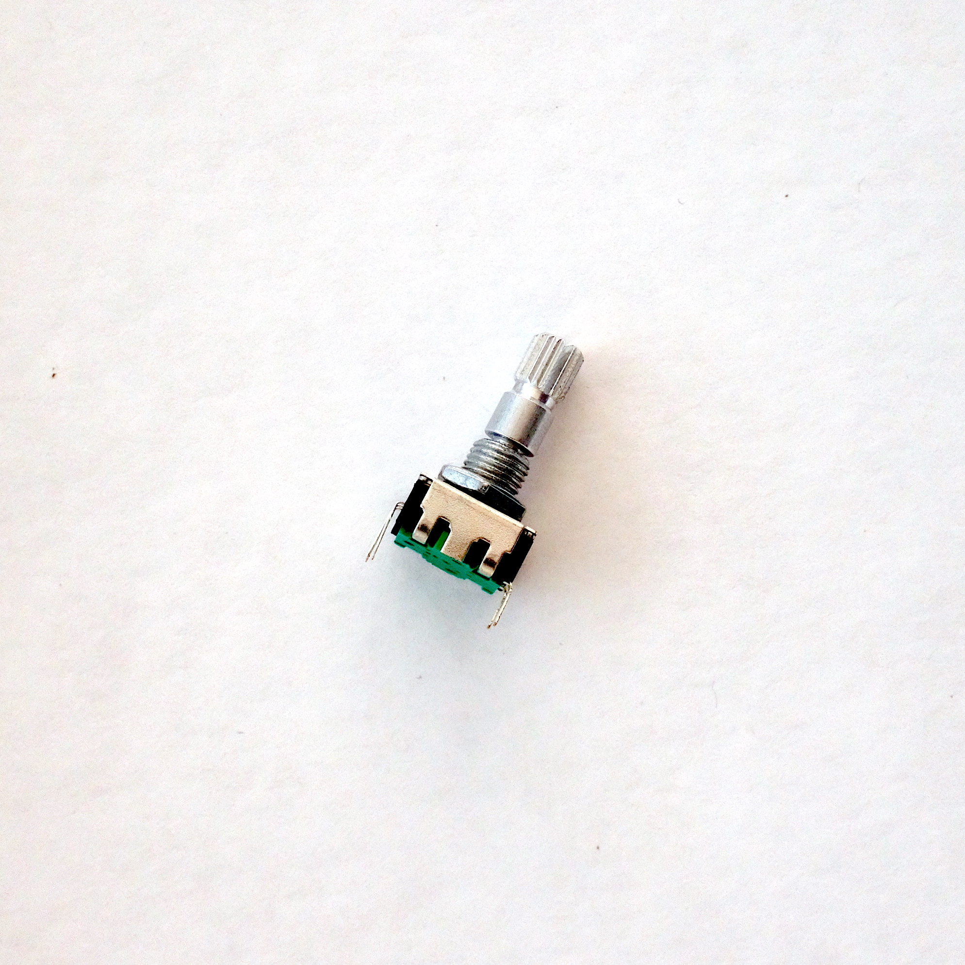
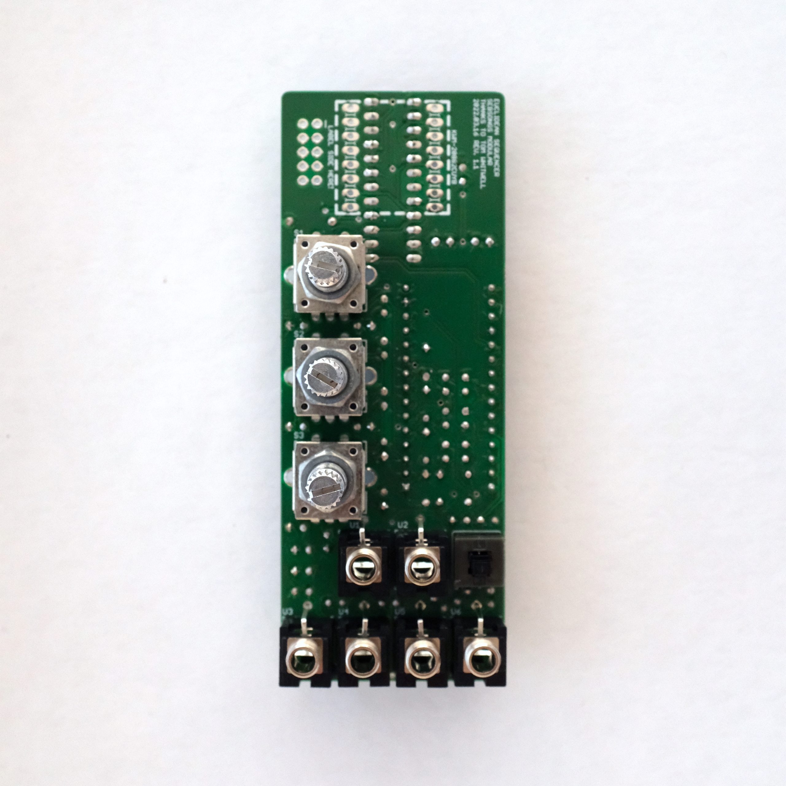
Flip the PCB around and solder the momentary switch (S4) to the board, making sure it is level with the board and aligned with the silk screen. There’s a small protruding line on one side that must point downwards, as indicated in the image above.OPTIONAL: Prepare the encoders for soldering by cutting the chassis tabs off level with the bottom of the encoder. This might not be necessary – check if the encoders fit the holes on the PCB. If so, skip this step.OPTIONAL: Encoders should look like this when the chassis tabs have been cut off. This might not be necessary – check if the encoders fit the holes on the PCB. If so, skip this step.Now is a good time to tighten the nut on each encoder. The nuts are used as a spacer between the encoder and the front panel. Place the encoders (S1, S2, S3) and the Thonkiconn jack sockets (U1, U2, U3, U4, U5, U6). Do not solder them yet!Fit the front panel over the encoders and jack sockets, and hand tighten all nuts. Make sure the PCB and panel are lined up with each other.Align the PCB so that the PCB and panel are in parallel to each other, and the distance between them is 10 millimeters. The jack sockets should have no gap to either PCB or panel.
The encoders must have a gap between the bottom of the encoders and the PCB, or the knobs will be situated too low in relation to the panel, and the encoder switches will not work. See image for reference.
Solder all pins belonging to encoders (S1, S2, S3) and the Thonkiconn jack sockets (U1, U2, U3, U4, U5, U6). Take care not to alter the alignment between the PCB and front panel while soldering.
6. 8×8 LED Matrix
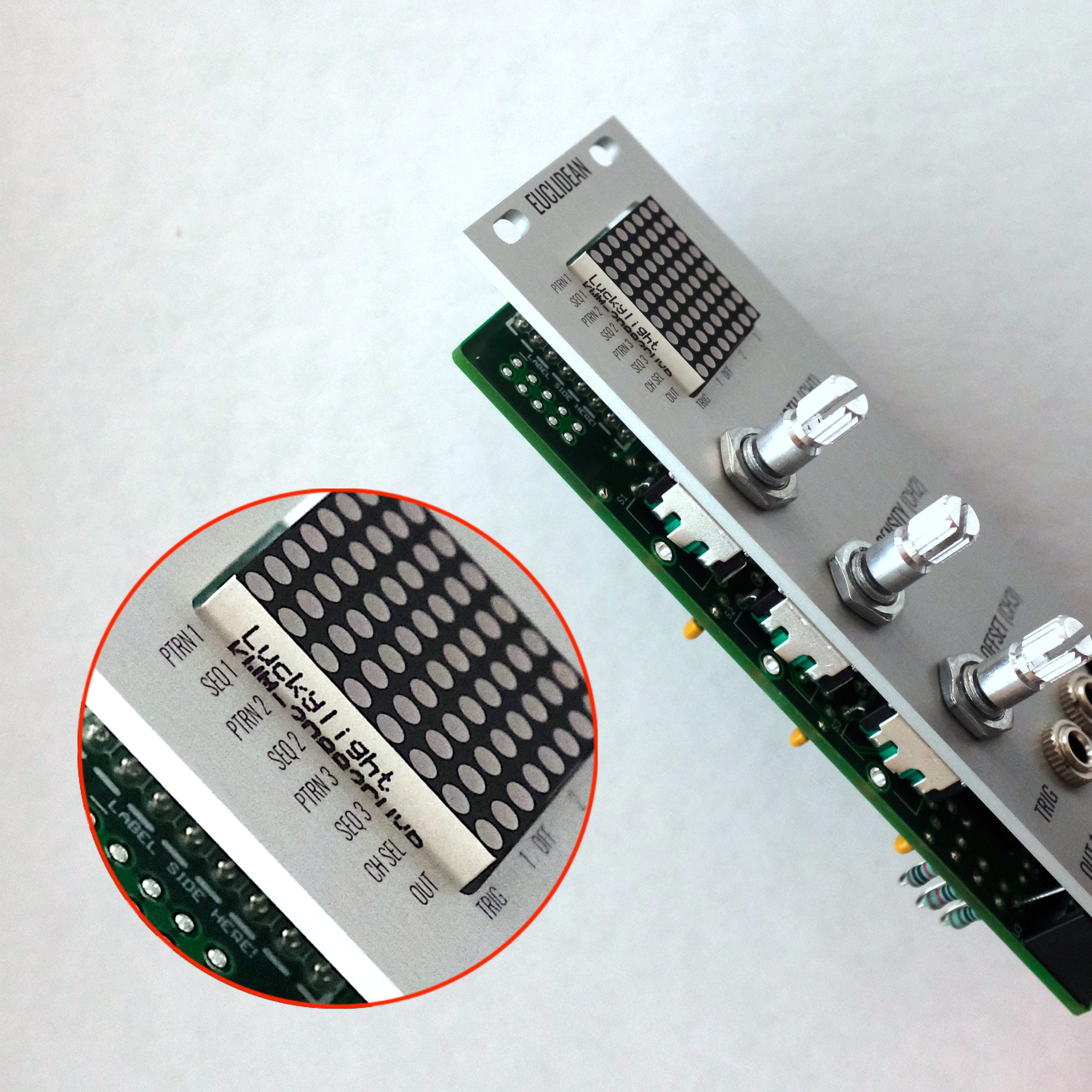
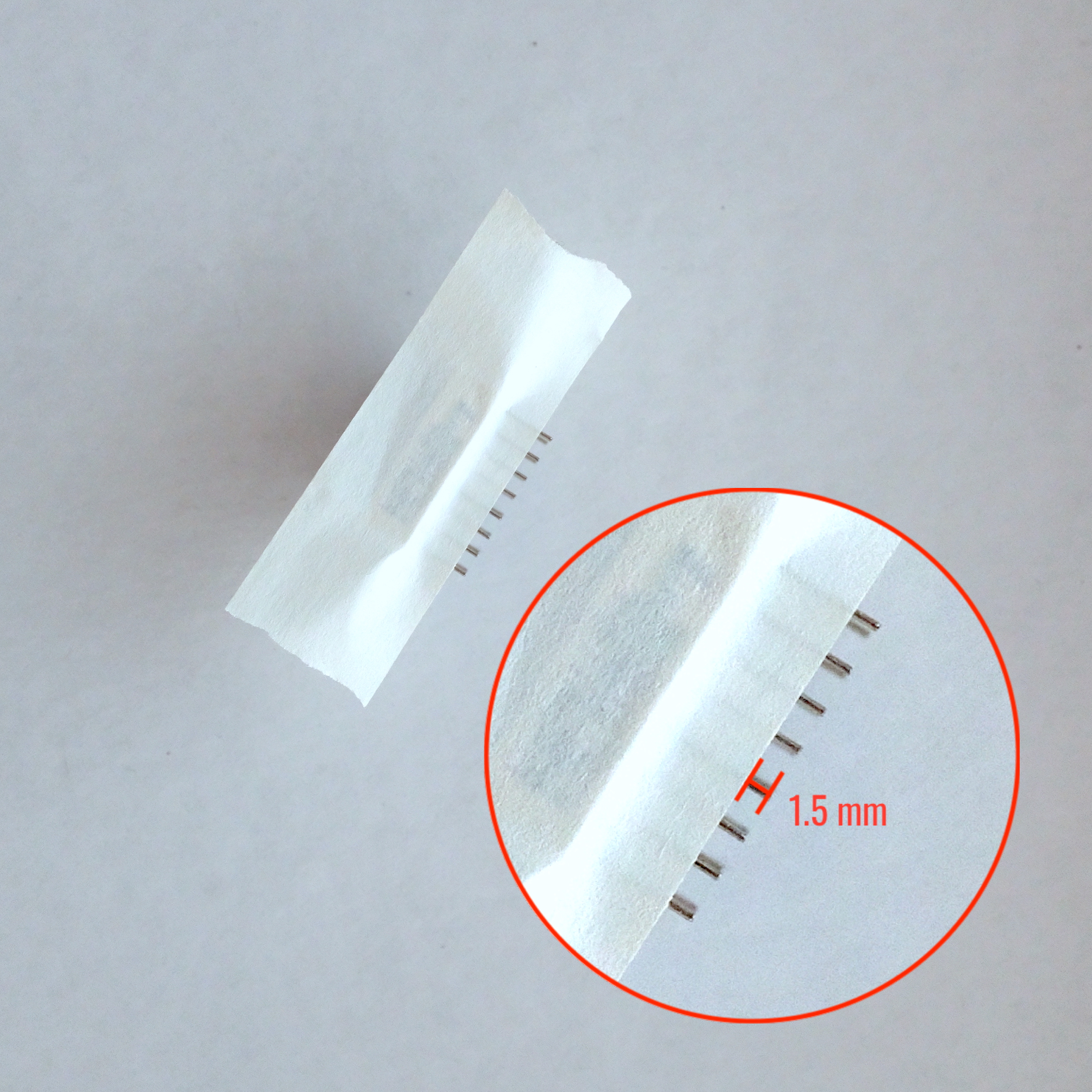
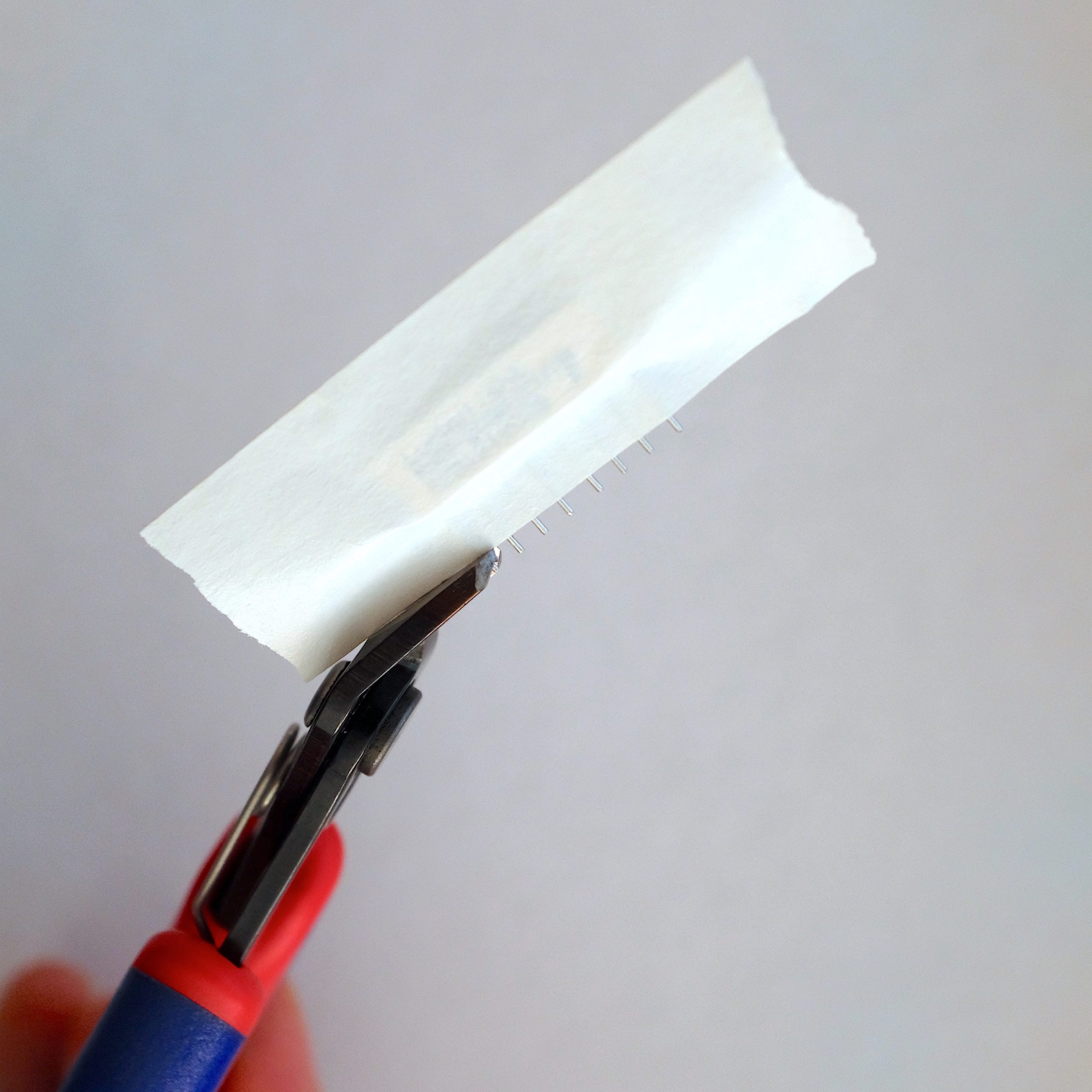
Cut the 40-pin female header into two 8-pin pieces. Press the female headers on to the pins of the 8×8 LED Matrix.Place the 8×8 LED Matrix with its headers into position on the PCB. Take care to align the label side of the 8×8 LED Matrix with the side on the PCB that says “LABEL SIDE HERE”. The 8×8 LED Matrix will protrude outside the front panel too much at this point. This is OK! Just make sure that the 8×8 LED Matrix is aligned with straigth in relation to the square in the front panel.Solder the 8×8 LED Matrix while making sure it still is correctly fitted as explained in the previous step. It is advisable to first solder two opposing corner pins and checking the alignment of the display before continuing to solder the rest of the pins. After soldering, deattach the 8×8 LED Matrix from the headers.Measure how far the 8×8 LED Matrix display protrudes from the edge of the front panel. In this case it was 1,5 millimeters. Mask off the pins of the 8×8 LED Matrix with some masking tape in preparation for cutting.Cut the excess length off the pins on the 8×8 LED Matrix. Take care not to cut too much!After cutting you can put the display back in its socket. Again, mind the orientation of the display.
7. Power connector
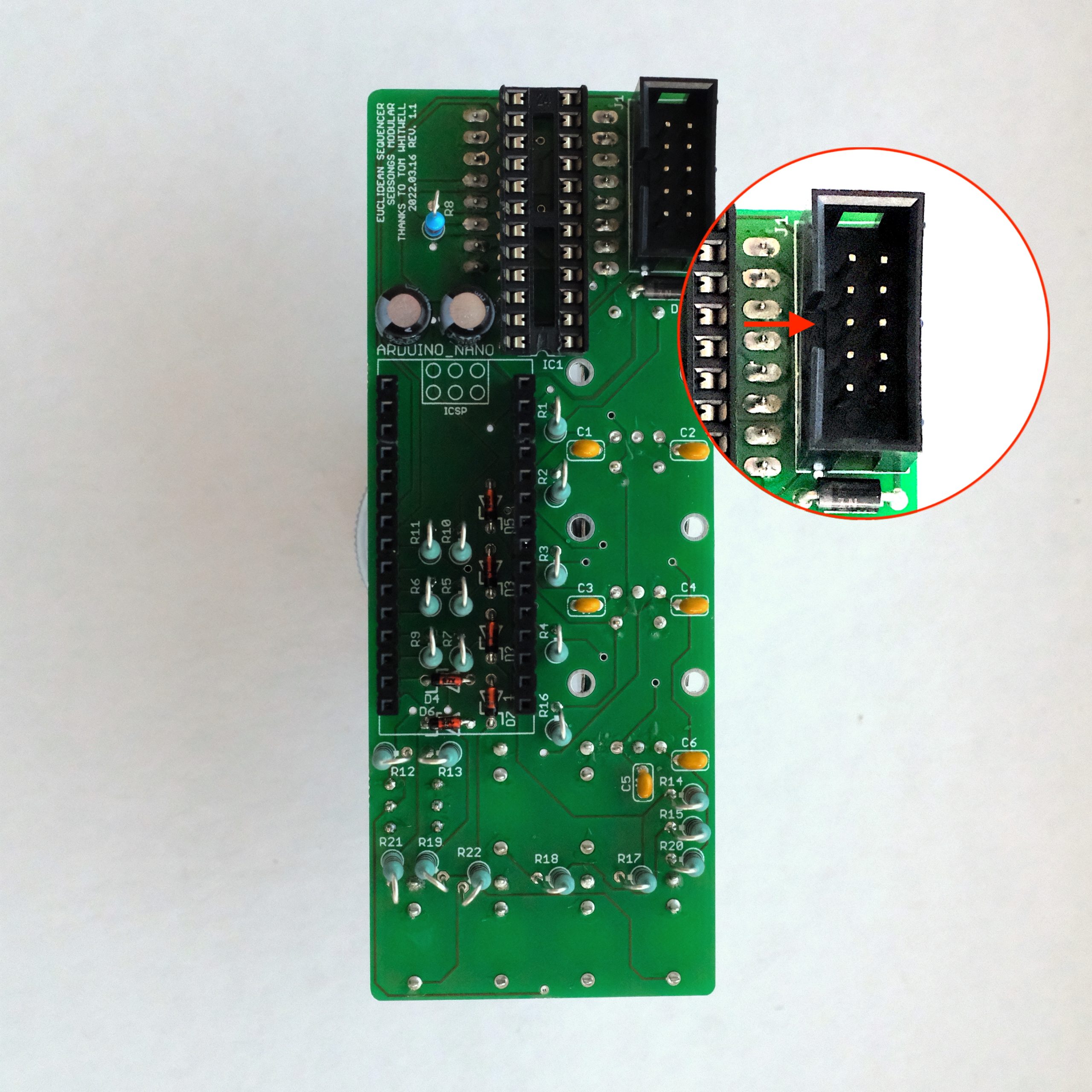
Remove the front panel again and solder the power connector (J1). Make sure it is oriented according to the silk screen! See image for reference.
8. Finishing up
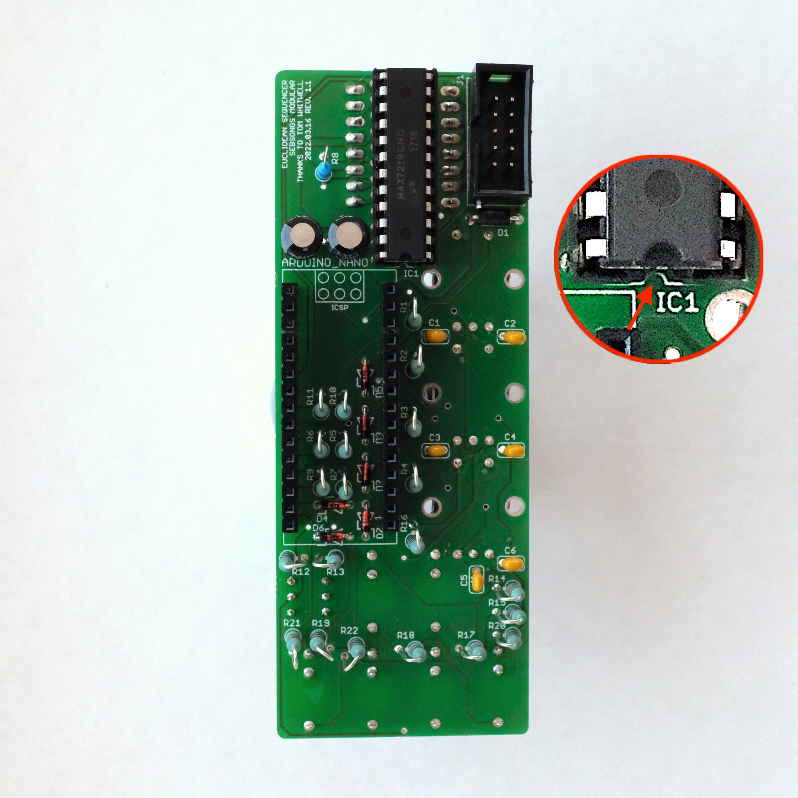
Seat the MAX7219 display driver chip in its socket (IC1), minding its orientation. See image above for orientation reference. Seat the Arduino Nano in its headers, minding the orientation. The Arduino only has one pin that can tolerate 12V (VIN), and should you power the module with the Arduino seated backwards you will feed 12V into an input that can not handle it! To make sure you don’t do this, here’s an extra warning:
WARNING! If you plug the Arduino in backwards it will likely not survive!
Attach the front panel to the board. This time, tighten the nuts with appropriate tools, taking care not to scratch the front panel.Attach the switch cap to the reset switch and teh three knobs to the encoder shafts. If your kit has brass adaptors then you’ll need to place these inside the knobs before screwing the knobs onto the encoder pots. You have now finished this build. Congratulations!
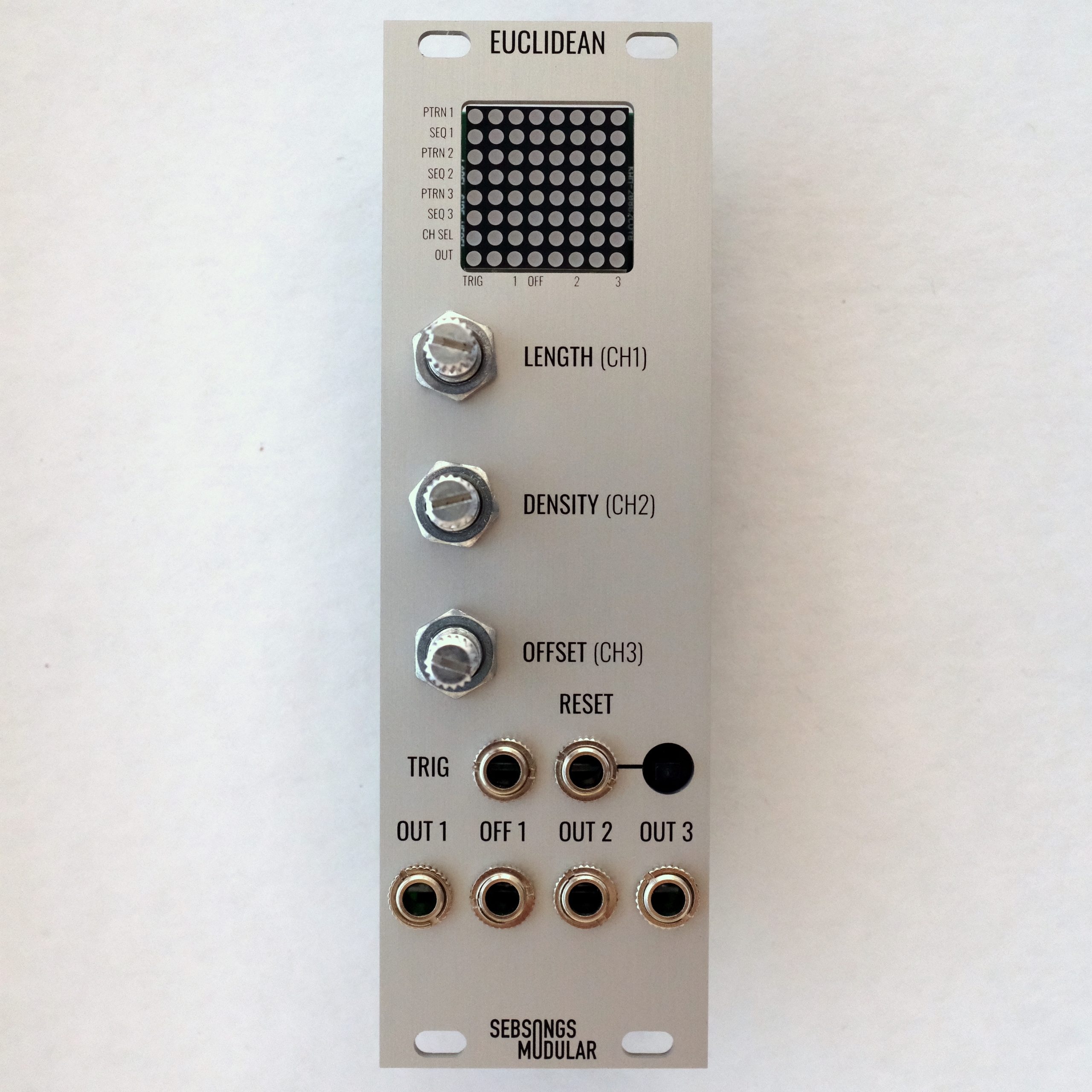
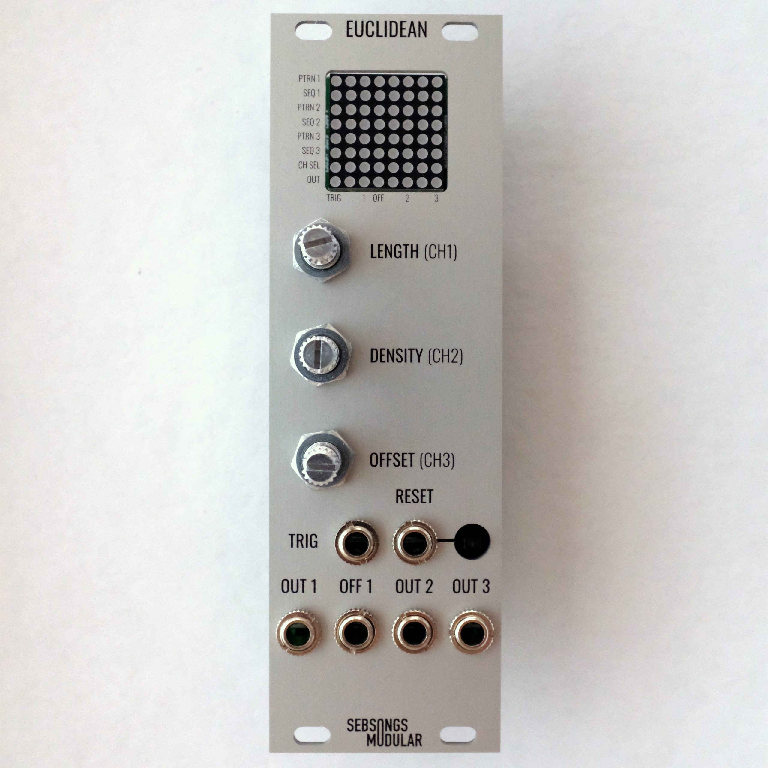
9. Powering up
Connect a 10-pin eurorack power cable to the power socket and attach the module in your eurorack case. At power-up, the 8×8 LED Matrix runs a short animation and then goes into sequencer mode. Try out all encoders (pushing them to select channel and turning them to change settings). Connect the outputs to modules that can be triggered by 5V gates, i.e. envelopes, drum modules etc. Also try the TRIG and RESET inputs using external sources such as LFOs or clock generators.