This build is an intermediate level build that contains surface mount components, and is not recommended for absolute beginners. If you are a beginner, it is recommended that you build something simpler before starting this project.
Note that the development board (Adafruit Pro Trinket) used in this module comes pre-programmed when purchased from Thonk.
Do this before building this module:
Check that you have all components.
Gather all the tools needed (see lists below).
The tools needed for this build are:
Soldering station or soldering iron.
High quality solder (lead free recommended).
Angled tweezers.
Fine tipped side cutters.
Recommended accessories:
PCB holder (makes life much easier).
Breadboard.
A fine grade file (for finishing off cut header edges).
10 mm hex socket covered in masking tape (for tightening nuts).
Knurled Nut Driver Tool (for tightening jack socket nuts).
Got everything? Let’s get on with it!
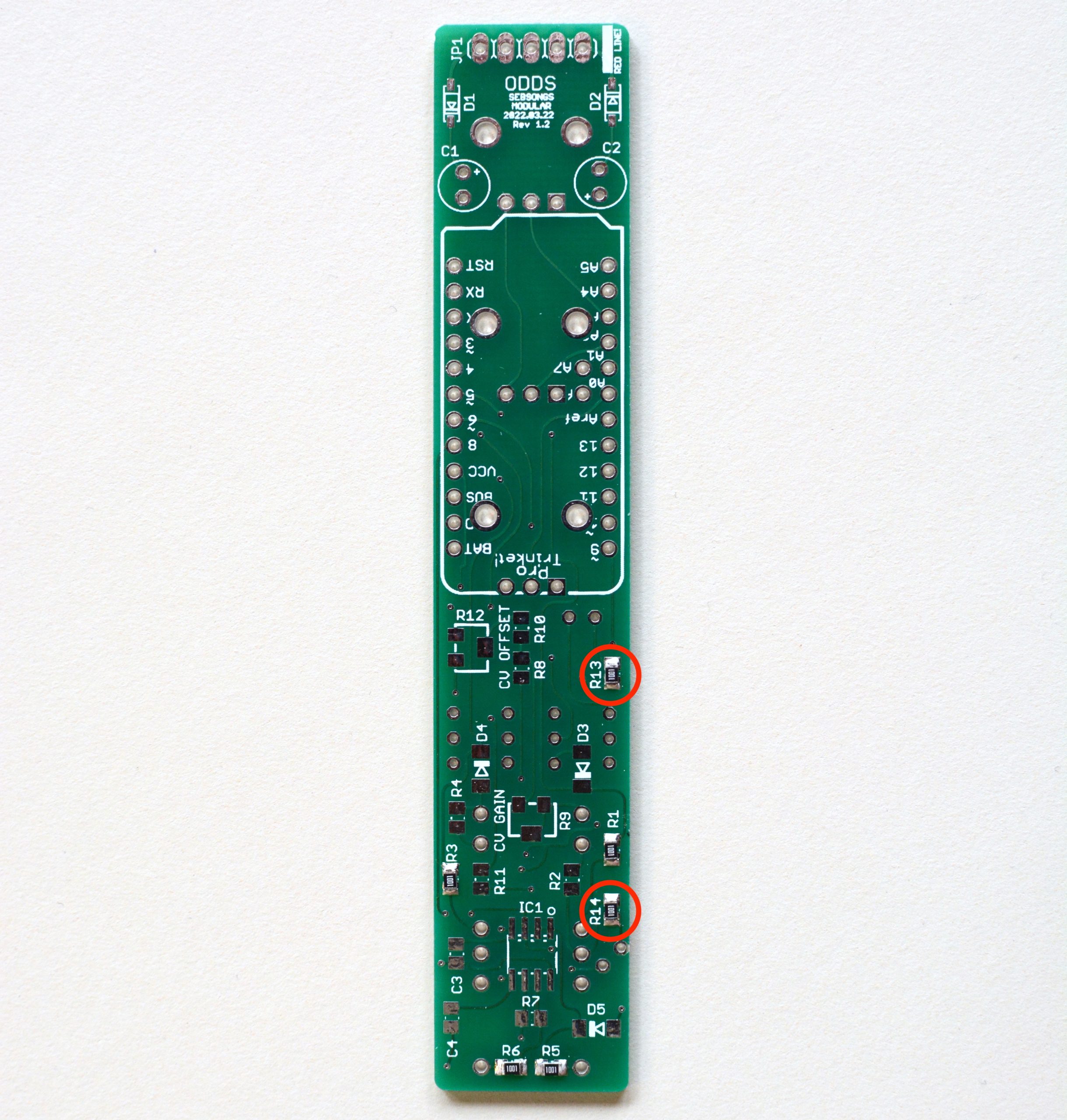
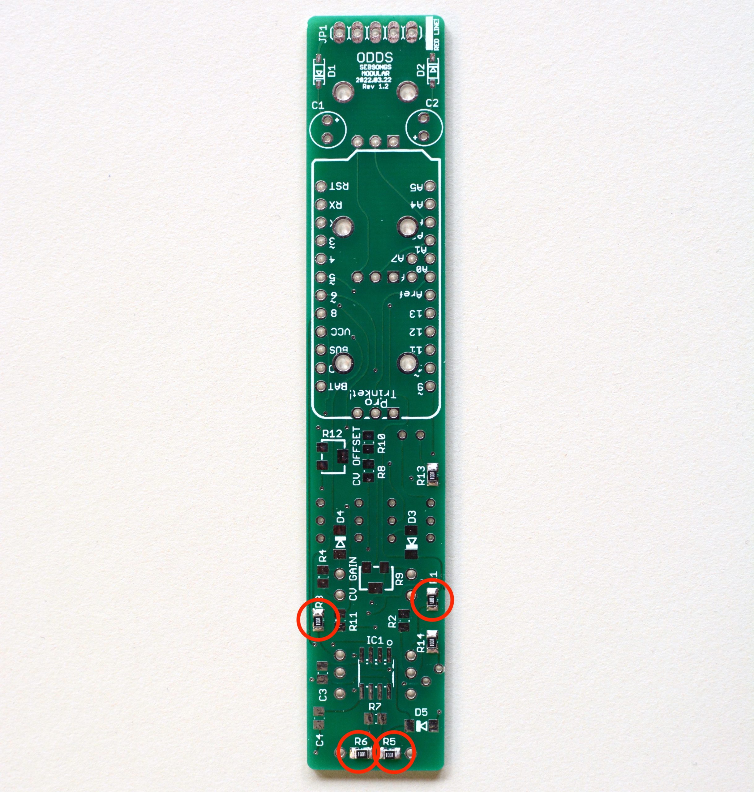
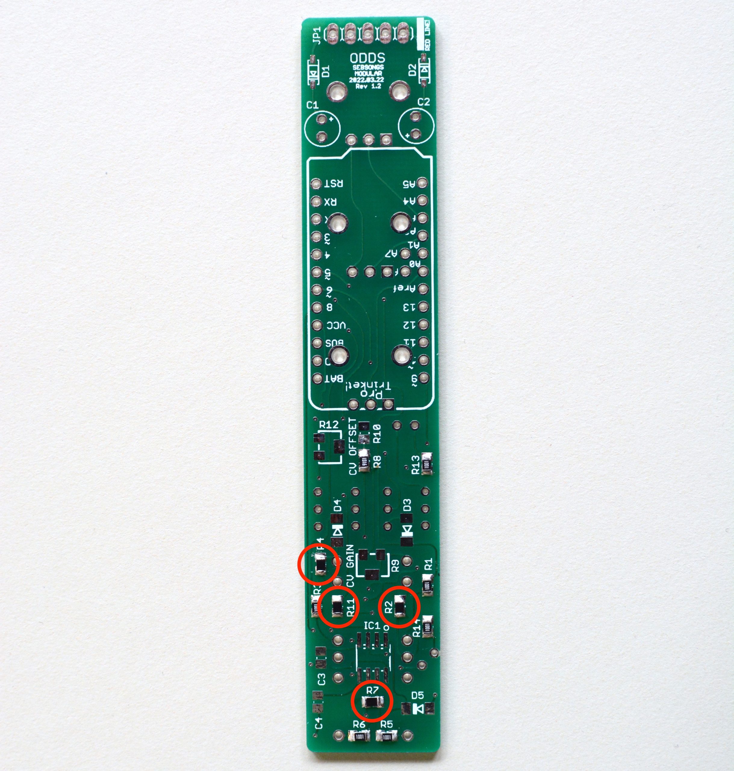
1. Resistors
Solder all 470R resistors (R13, R14).
Solder all 1K resistors (R1, R3, R5, R6).Solder the 9K1 resistor (R8).Solder all 10K resistors (R2, R4, R7, R11).Solder the 100K resistor (R10)
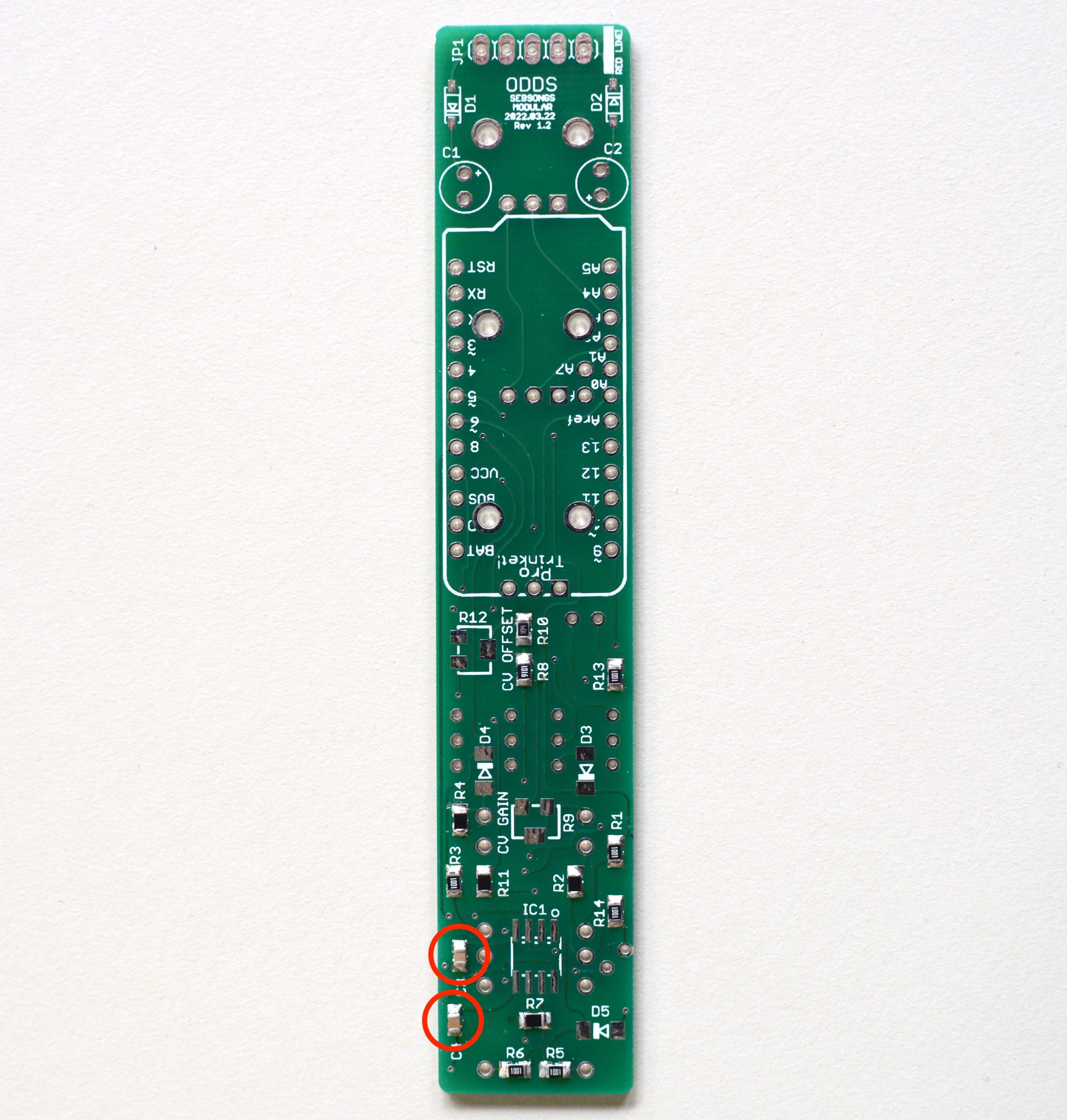
2. Capacitors
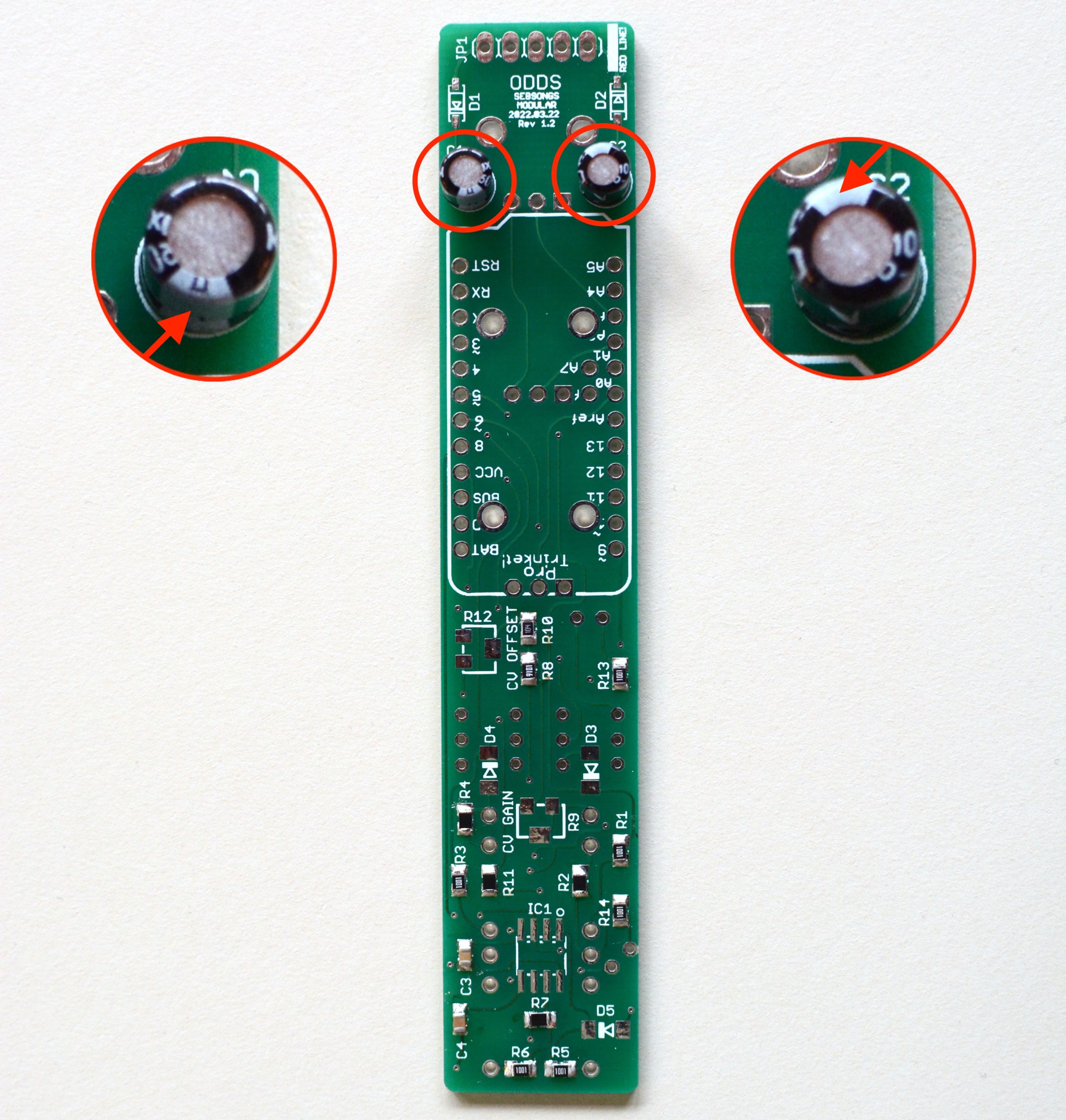
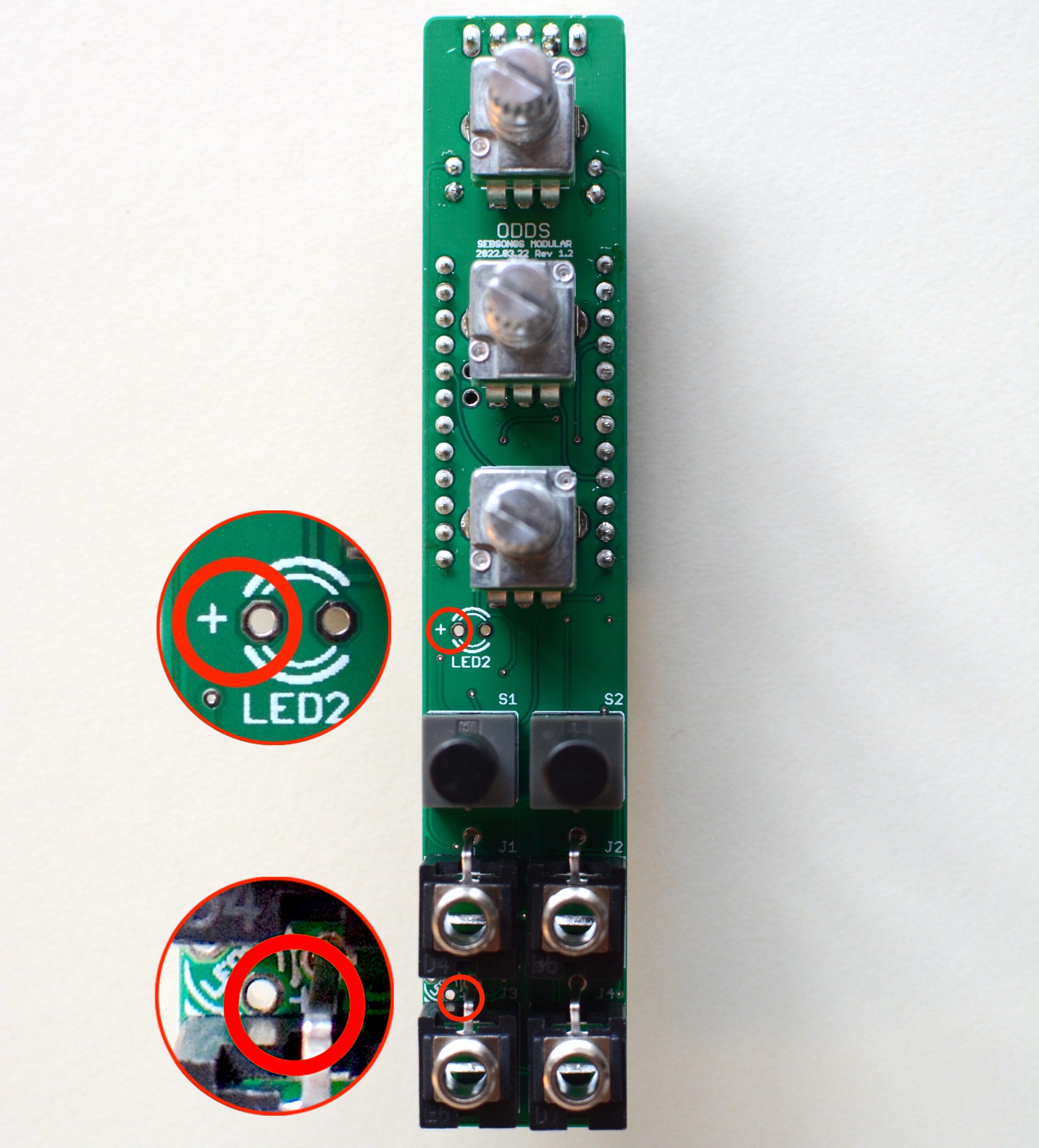
Solder the 100nF ceramic capacitors (C3, C4). Solder the 10uF electrolytic capacitors (C1, C2). Make sure to check the polarity twice before soldering, the long leg must go to the hole with the plus symbol! See image for reference. Remember to cut the excess legs after soldering.
3. Diodes
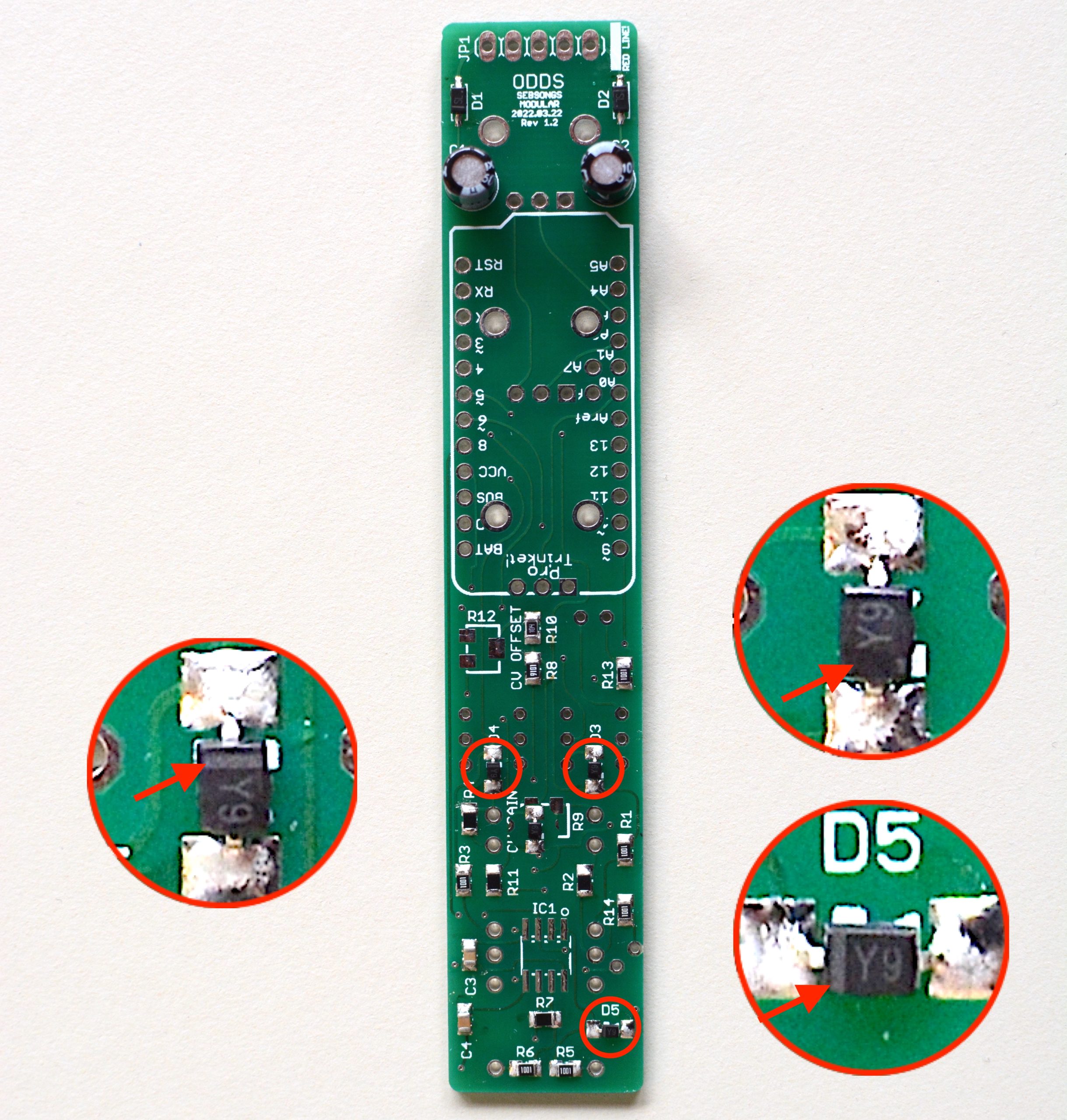
Solder the 1N5819 schottky diodes (D1, D2). Make sure to check the polarity twice before soldering. See image for reference.Solder the 5V1 zener diodes (D3, D4, D5). Make sure to check the polarity twice before soldering. See image for reference.
4. ICs
Solder the TL072 operational amplifier (IC1). It is advisable to mount the IC by first soldering one corner pin, to make sure the chip is well aligned on the PCB. When it is, solder the diagonally opposing corner pin, and then the rest of the pins. Make sure to check the orientation twice before soldering. See image for reference.
5. Trimmers
Solder the 2K trimmer (R9).Solder the 100K trimmer (R12).
6. Switch, jacks sockets and potentiometers
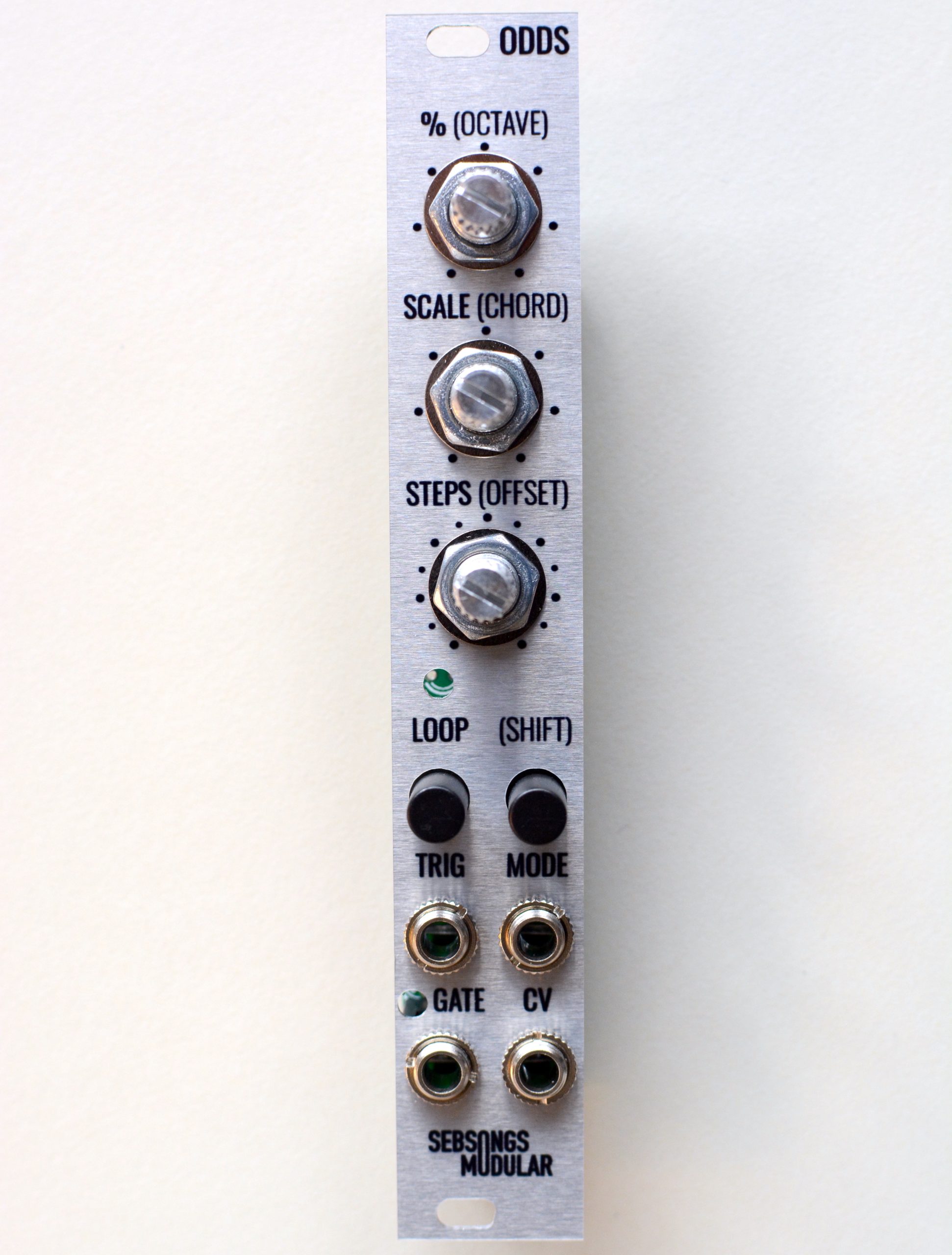
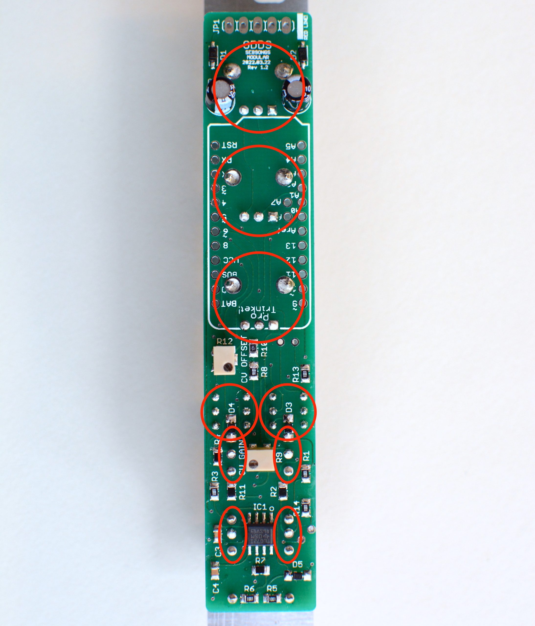
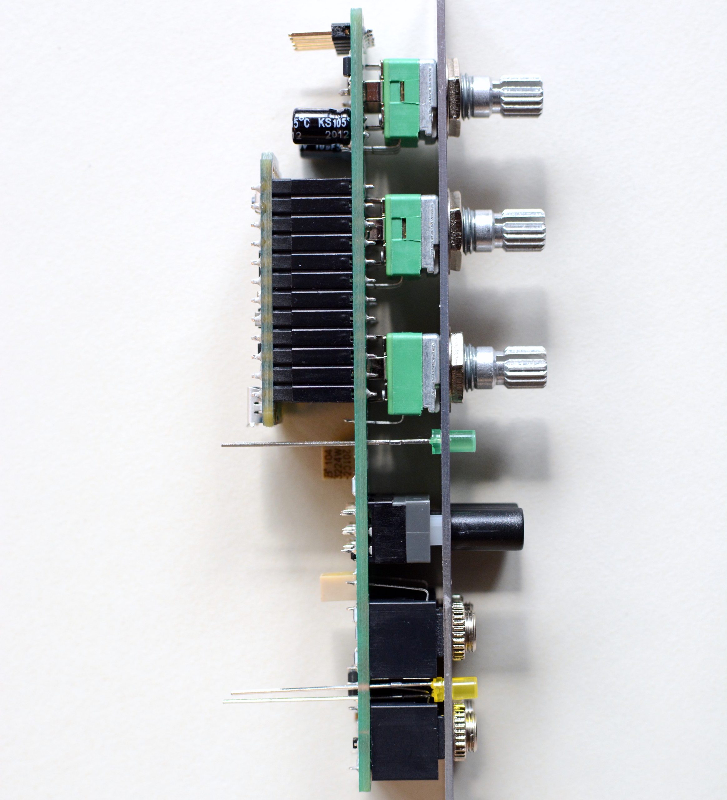
Place the 10K potentiometers (VR1, VR2, VR3), the WHITE ON-ON Latching Switch (S1), the BLACK ON-(ON) Non Latching Switch (S2) and the Thonkiconn jack sockets (J1, J2, J3, J4). Make sure that both switches have their protruding lines pointing down towards the jacks, i.e. align the switches with the silk screen.Do not solder anything yet!Fit the front panel over the potentiometers and jack sockets, and hand tighten all nuts. Fit the caps for the switches. Make sure the PCB and panel are lined up with each other.Turn the whole thing around and solder all joints as marked in the image above.
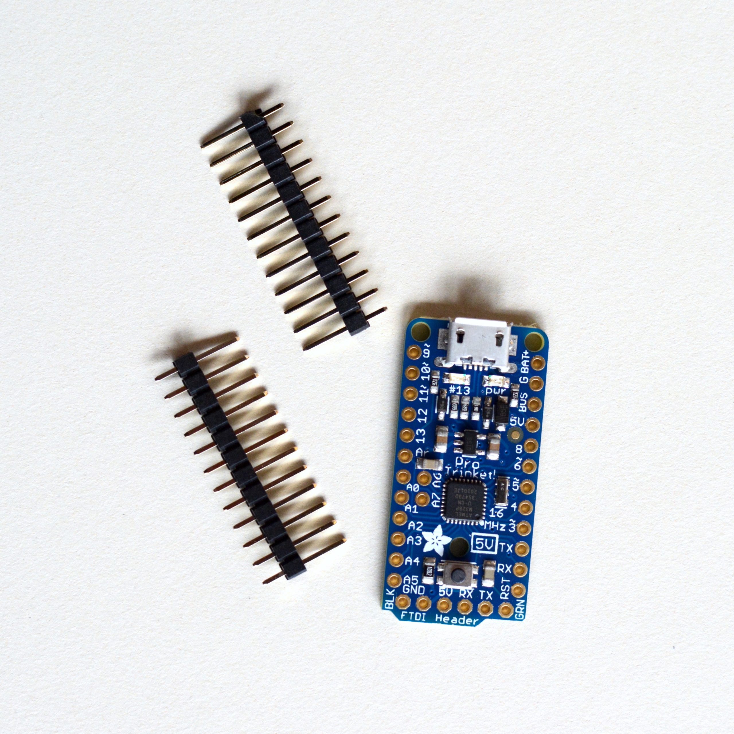
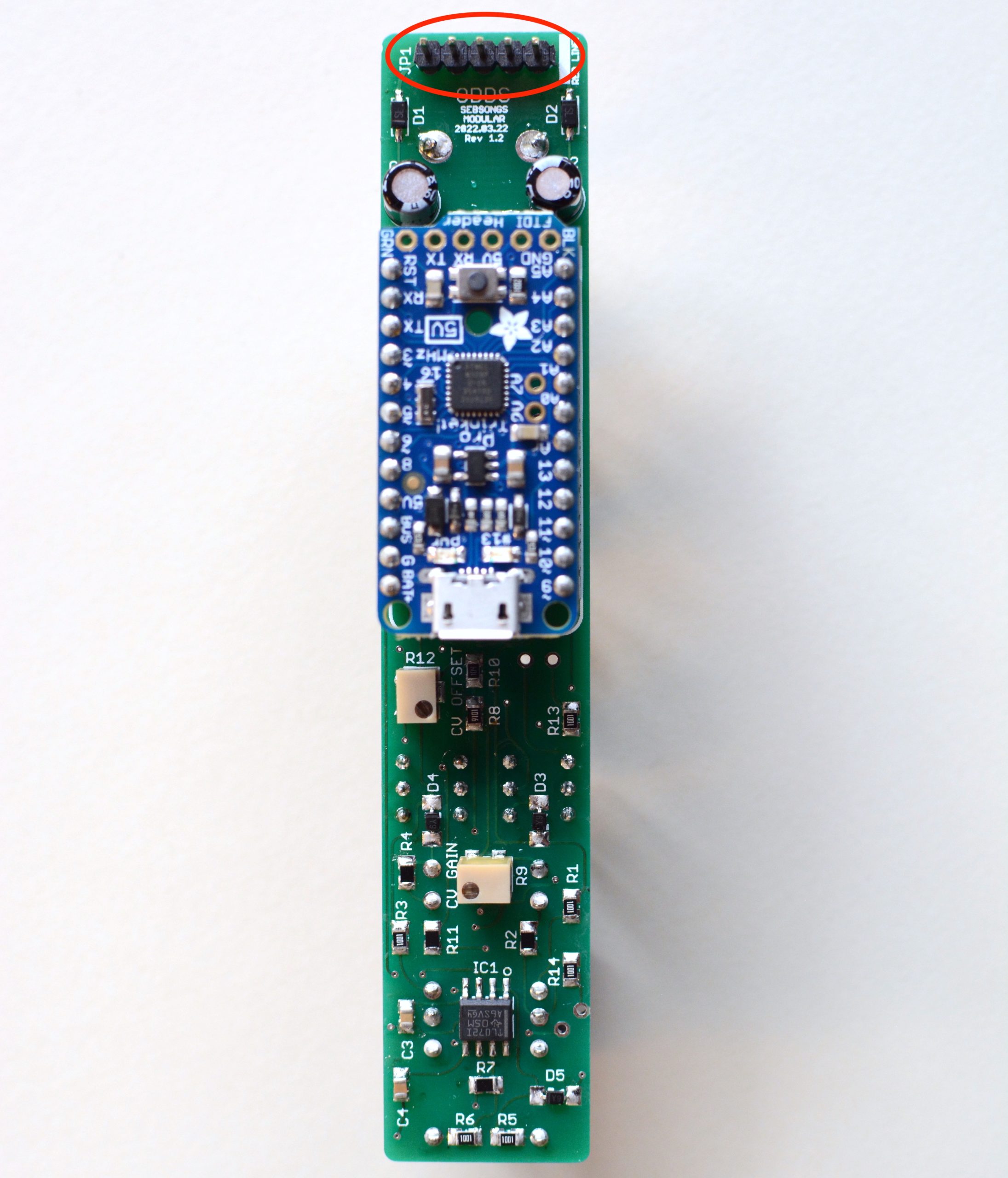
7. Adafruit Pro Trinket 5V
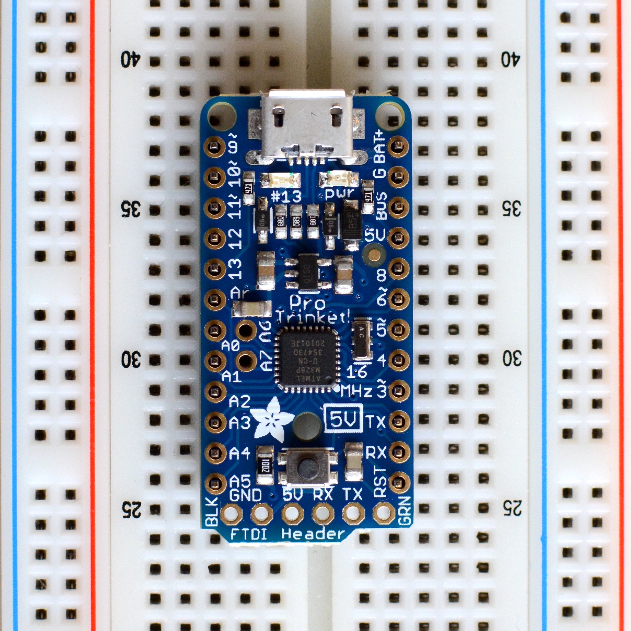
Take out the Adafruit Pro Trinket 5V and the 12 pin headers.Place the headers in a breadboard and fit the Pro Trinket so it aligns correctly with the headers.Solder all 24 header pins to the Pro trinket. Start with two diagonally opposing corners pins, and then make sure alignement is good. Continue soldering the rest of the pins.Attach the 12 pin female headers to the headers on the Pro Trinket.Seat the Pro Trinket in the correct orientation on the PCB. The Pro Trinket only has one pin that can tolerate 12V (BAT+), and should you power the module with the Pro Trinket seated backwards you will feed 12V into an input that can not handle it! To make sure you don’t do this, here’s an extra warning:
WARNING! If you plug the Pro Trinket in backwards it will likely not survive!
Solder all 24 header pins to the PCB. Start with two diagonally opposing corners pins, and then make sure alignement is good. Continue soldering the rest of the pins.
8. Power Header
Flip the board over again and solder the 1×5 pin header for the eurorack power connector.
9. LEDs
Attach the LEDs to the corresponding placements. LED1 is YELLOW and LED2 is GREEN. Make sure the orientation of the LEDs are correct! The long leg is +.After putting the LEDs in the correct places, fit the front panel and tighten the nuts. Push each LED through its corresponding hole in the panel.Push each LED back so it aligns perfectly with the front panel.Making sure the LEDs align with the panel, solder the LEDs and cut off the excess legs. You are now done with the assembly!
10. Powering up
First, make sure that the Pro Trinket is seated in the correct orientation on the PCB (USB socket facing downwards). Then connect a 10-pin eurorack power cable to the power socket (MAKE SURE THE ORIENTATION IS CORRECT!) and attach the module in your eurorack case. Push the LOOP switch and see if the GREEN LED is turning on. To test the module, connect an LFO to the TRIG input and a synth voice to the CV/GATE outputs. Increase the probability to start generating notes. The module should now be generating random melodies, although the notes are probably not in tune.
11. Calibration
To calibrate the CV output, hold the SHIFT switch while powering on the module, and hold it until the yellow LED flashes twice. ODDS is now in calibration mode. To calibrate, set the % knob to the leftmost position. Connect a multimeter measuring DC voltage to the CV output. Adjust the CV OFFSET trimmer on the PCB until the multimeter reads 0.00 Volts. Now set the % knob to the rightmost position. The multimeter should read 6.00 Volts. If it does not, adjust the CV GAIN trimmer until it does. Redo this procedure a couple of times until both values are correct. Connect an oscillator to the CV output. Sweep the % knob to confirm that the octaves sound correct in pitch. To exit calibration mode, power off your case and power it back on without holding the SHIFT switch.