This is a quite straightforward build, as all surface mount components come pre soldered, however the layout is pretty tight so care has to be taken to avoid melting the plastic on the headers when soldering the through hole components.
Do this before building this module:
Check that you have all components.
Gather all the tools needed (see lists below).
The tools needed for this build are:
Soldering station or soldering iron.
High quality solder (lead free recommended).
Fine tipped side cutters.
Recommended accessories:
PCB holder (makes life much easier).
Breadboard.
Knurled Nut Driver Tool (for tightening jack socket nuts).
10 mm and 11 mm hex sockets covered in masking tape (for tightening nuts).
Got everything? Let’s get on with it!
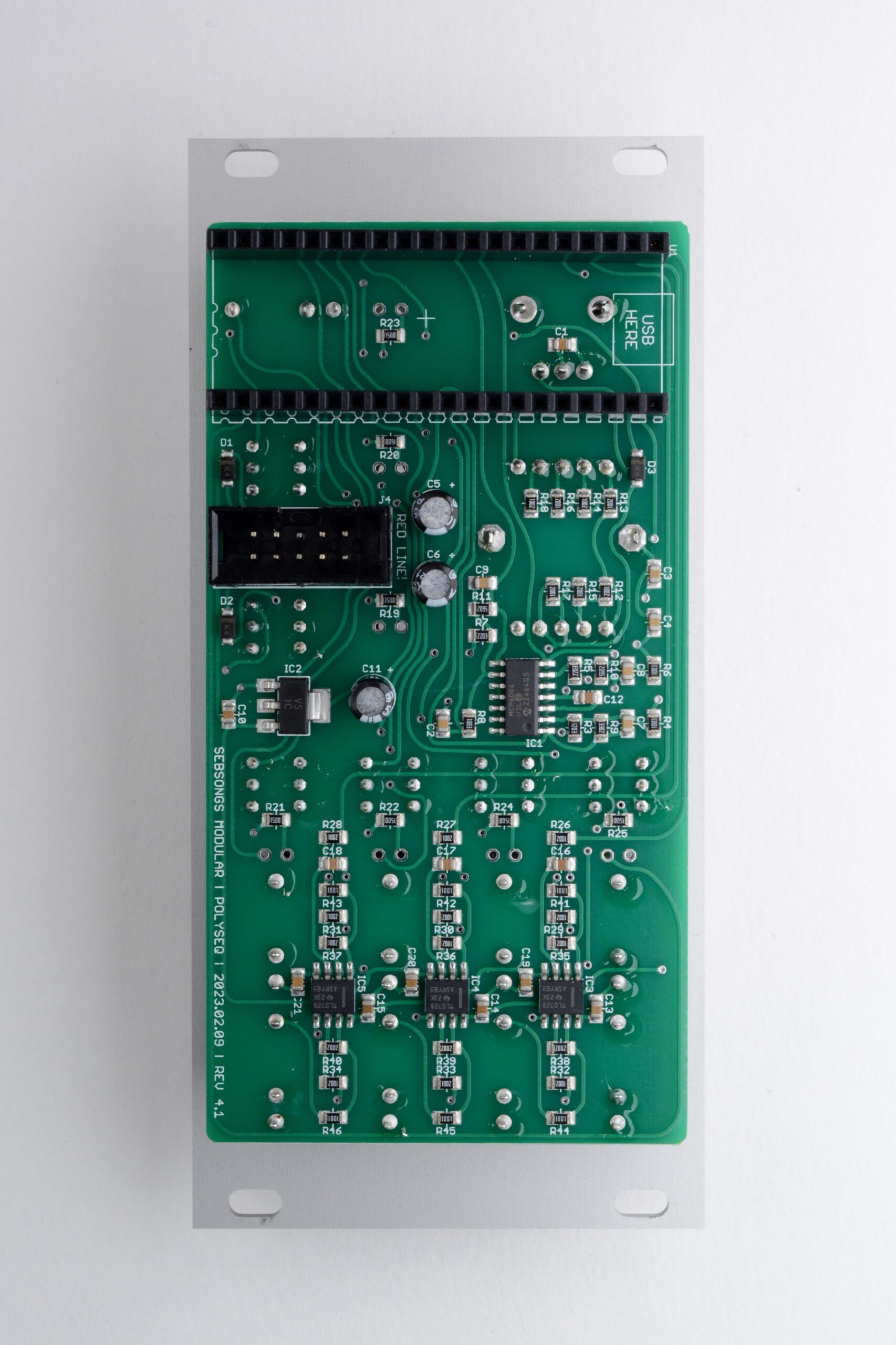
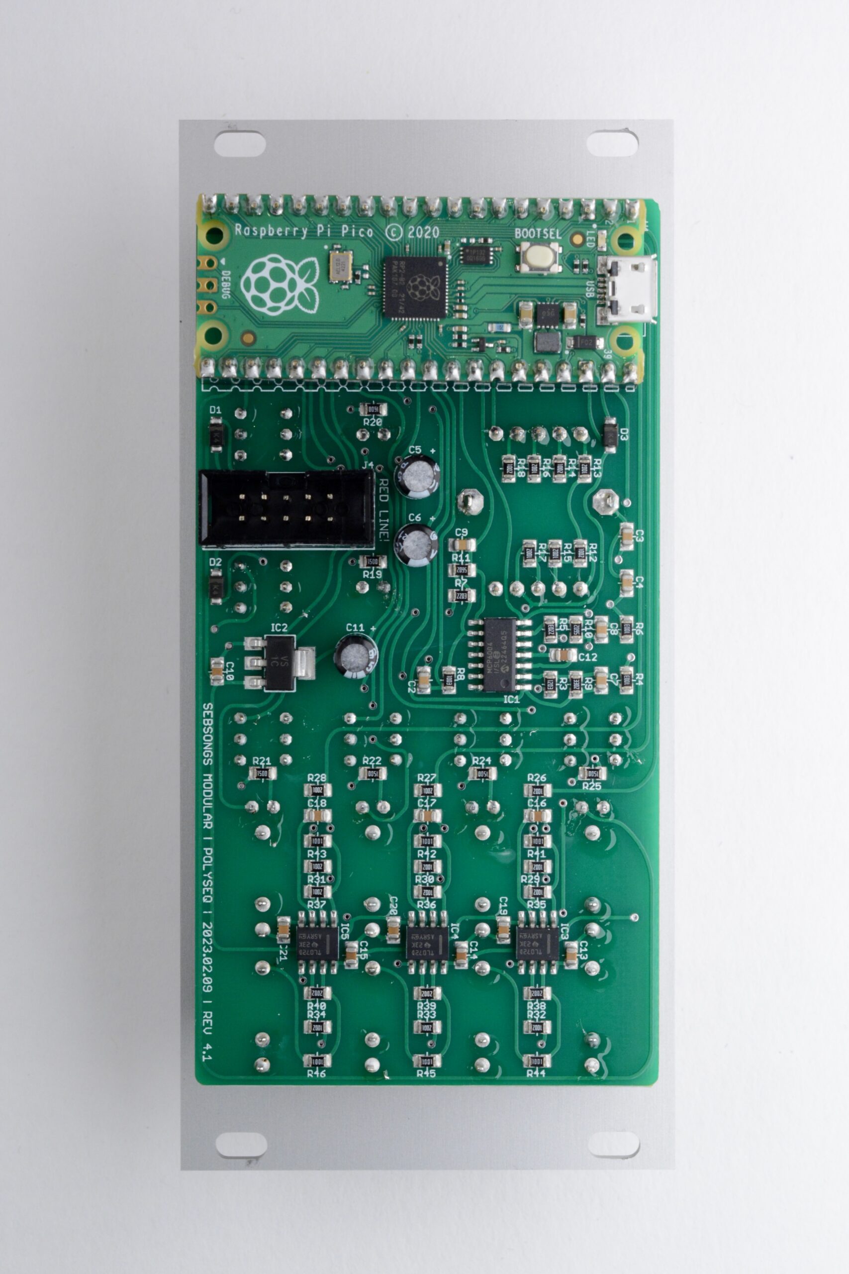
1. Capacitors
Begin by soldering the 10uF electrolytic capacitors (C5, C6, C11). Make sure to check the polarity twice before soldering, See image for reference.
2. Headers
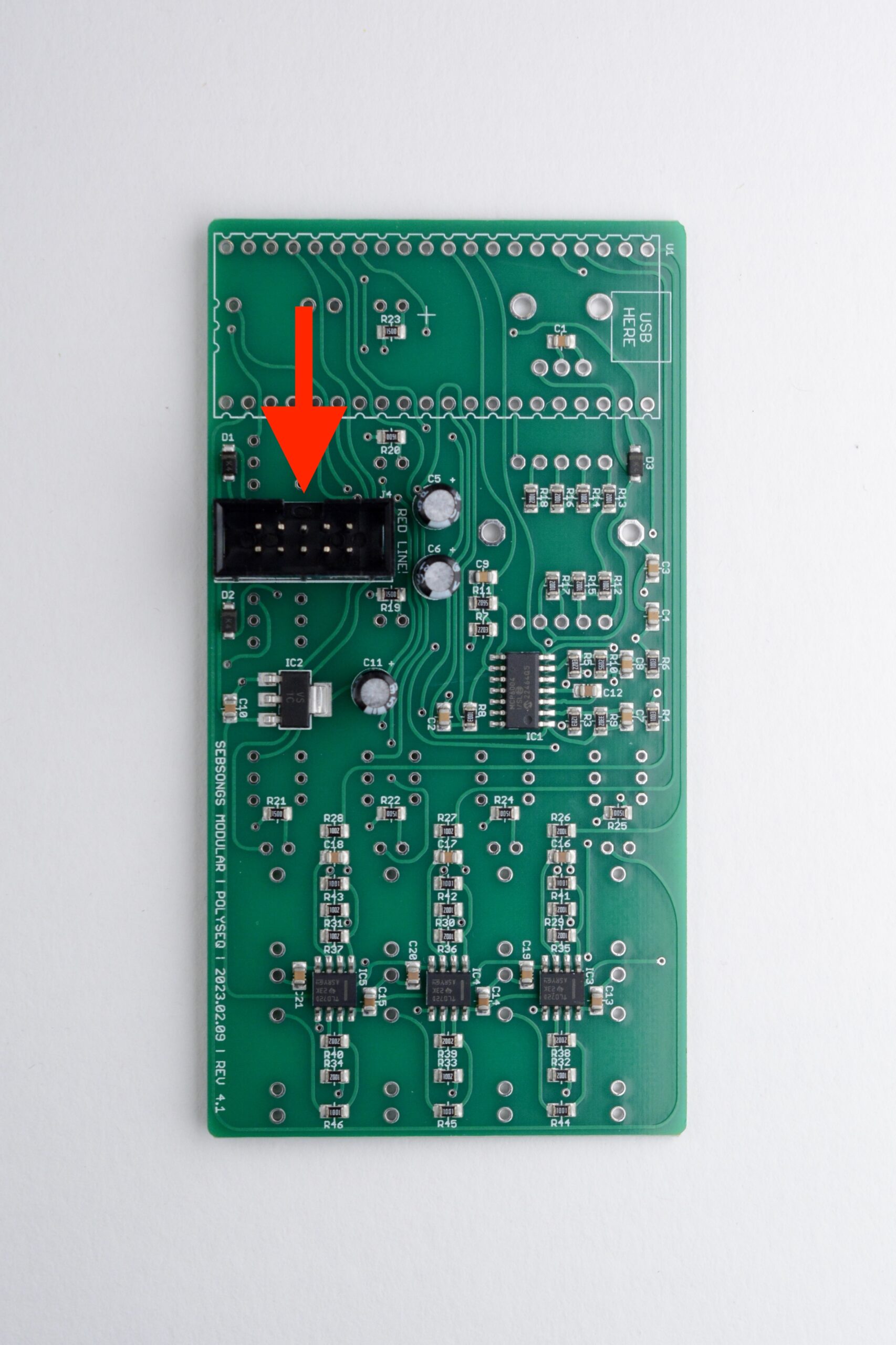
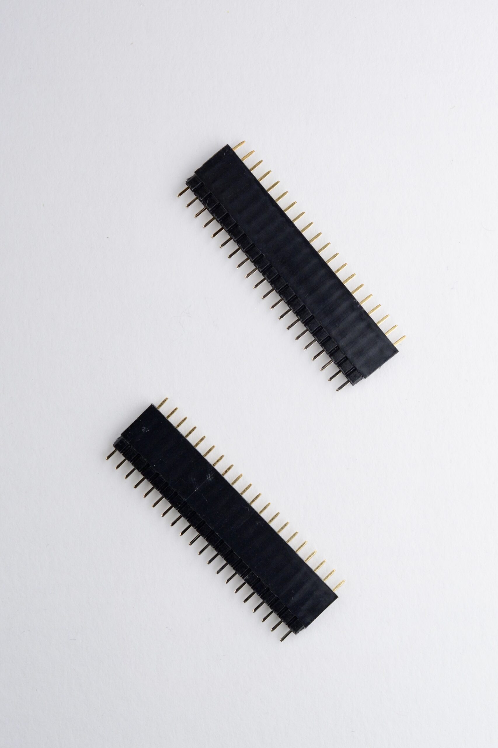
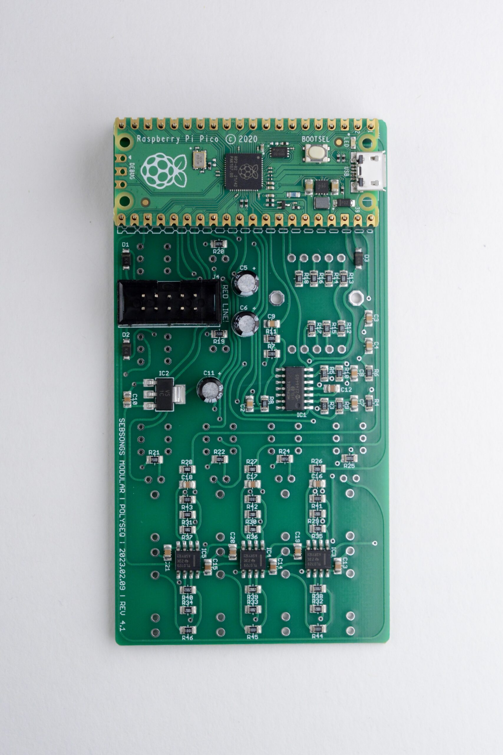
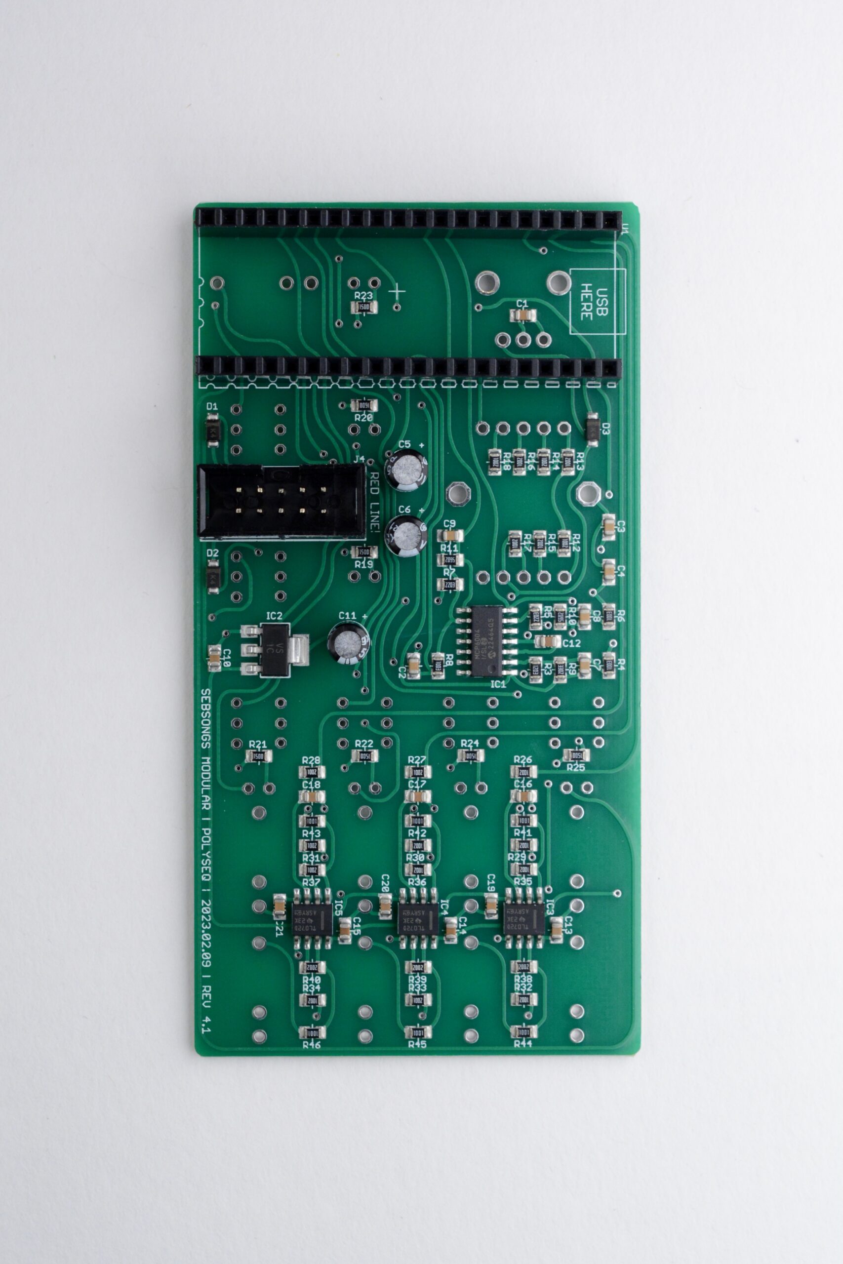
Solder the power connector (J4). Make sure it is oriented according to the silk screen! See image for reference.Fit the 20-pin pin headers with the 20-pin sockets as shown in the image.Place the fitted headers on the PCB with the sockets facing down towards the PCB and the pin headers facing up. Place the Raspberry Pi Pico on the pin headers and make sure it lies flat against the pin headers.Solder all 40 joints on the Raspberry Pi Pico. Then solder the header sockets to the PCB while the Raspberry Pi Pico is still attached to the headers. After soldering all 40 joints on the PCB, remove the Raspberry Pi Pico to find the header sockets attached to the PCB.
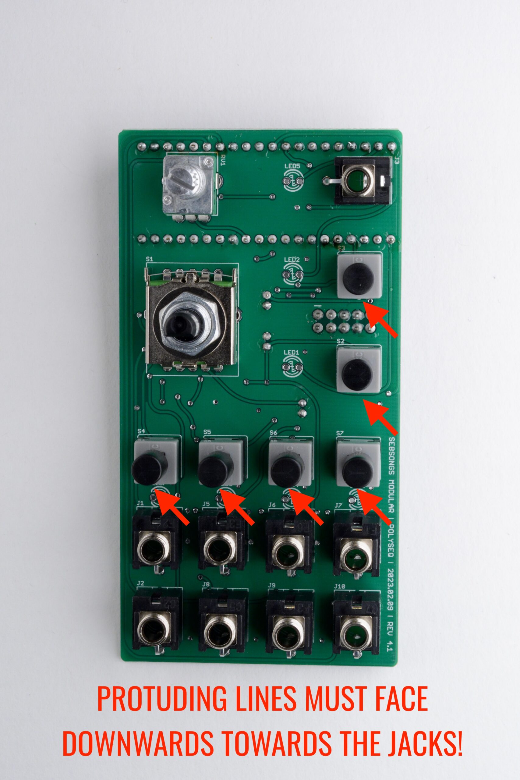
3. Potentiometer, switches and jacks
Flip the PCB over and place all jacks, potentiometer, rotary switch and momentary switches. Make sure that the six momentary switches have their protruding lines pointing down towards the jacks, i.e. align the switches with the silk screen!Fit the front panel and hand tighten all knobs. Solder all the joints for the jacks, switches and potentiometer. Make sure to push the momentary switches against the PCB when soldering them.
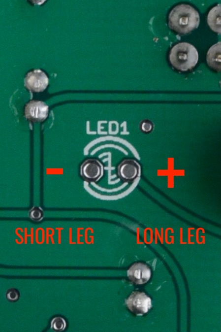
4. LEDs
Undo all nuts and take off the front panel. Place the right LED in its corresponding position. The colors should be fitted in the following order from top to bottom: YELLOW, RED, GREEN, ORANGE x4. Make sure to get the polarity of the LEDs right. The flat side of the silkscreen symbol is the short leg of the LED and the round side is the long leg of the LED. See image for reference.Fit the front panel to the jacks, switches and potentiometer again, and push the LEDs out their corresponding hole. Don’t solder them yet!Put the whole module on its side and try to push the LEDs in so that they are flush with the front panel. You can use masking tape to make this process easier. Solder the LEDs when you have them flush with the front panel.
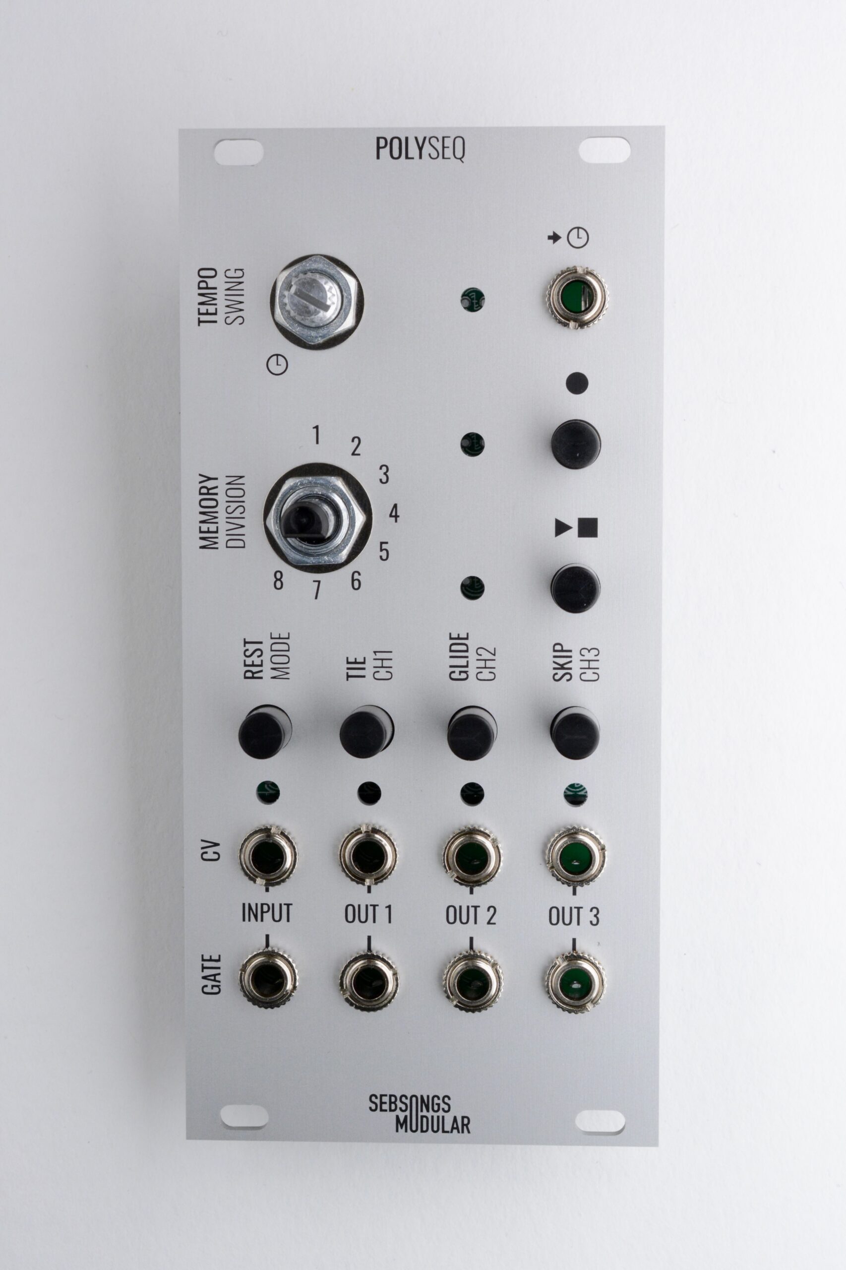
5. Finishing up
Fit the Raspberry Pi Pico in its sockets, minding its orientation. See image and PCB silkscreen for reference.Tighten all nuts with appropriate tools and fit the two knobs on the potentiometer and the rotary switch. You are done!
6. Powering up and testing
Before powering on, measure resistance with a multimeter between ground and + and – respectively on the power connector to make sure there are no short circuits. The resistance should be several kilo Ohms and the value should climb as the multimeter charges the capacitors.
At first power on, hold the MODE and RECORD switches for a couple of seconds until the red RECORD LED blinks. This is for initialising the sequencer memory.
Connect a CV/GATE keyboard to the CV/GATE inputs. Press RECORD and play some notes. Now press PLAY and your sequence should play back if you have a synth voice connected to any of the CV/GATE outputs. Note that when recording sequences, the notes are only monitored on CH1. Have fun with your new sequencer!