This build is an intermediate level build, not recommended for absolute beginners. If you are a beginner, it is recommended that you do an easier build before starting this project.
Note that the development board (Adafruit Itsybitsy RP2040) used in this module comes pre-programmed when purchased from Thonk.
Do this before building this module:
Check that you have all components.
Gather all the tools needed (see lists below).
The tools needed for this build are:
Soldering station or soldering iron.
High quality solder (lead free recommended).
Fine tipped side cutters.
Angled tweezers.
Philips head screwdriver.
Recommended accessories:
PCB holder (makes life much easier).
Breadboard.
A fine grade file (for finishing off cut header edges).
Knurled Nut Driver Tool (for tightening jack socket nuts).
Got everything? Let’s get on with it!
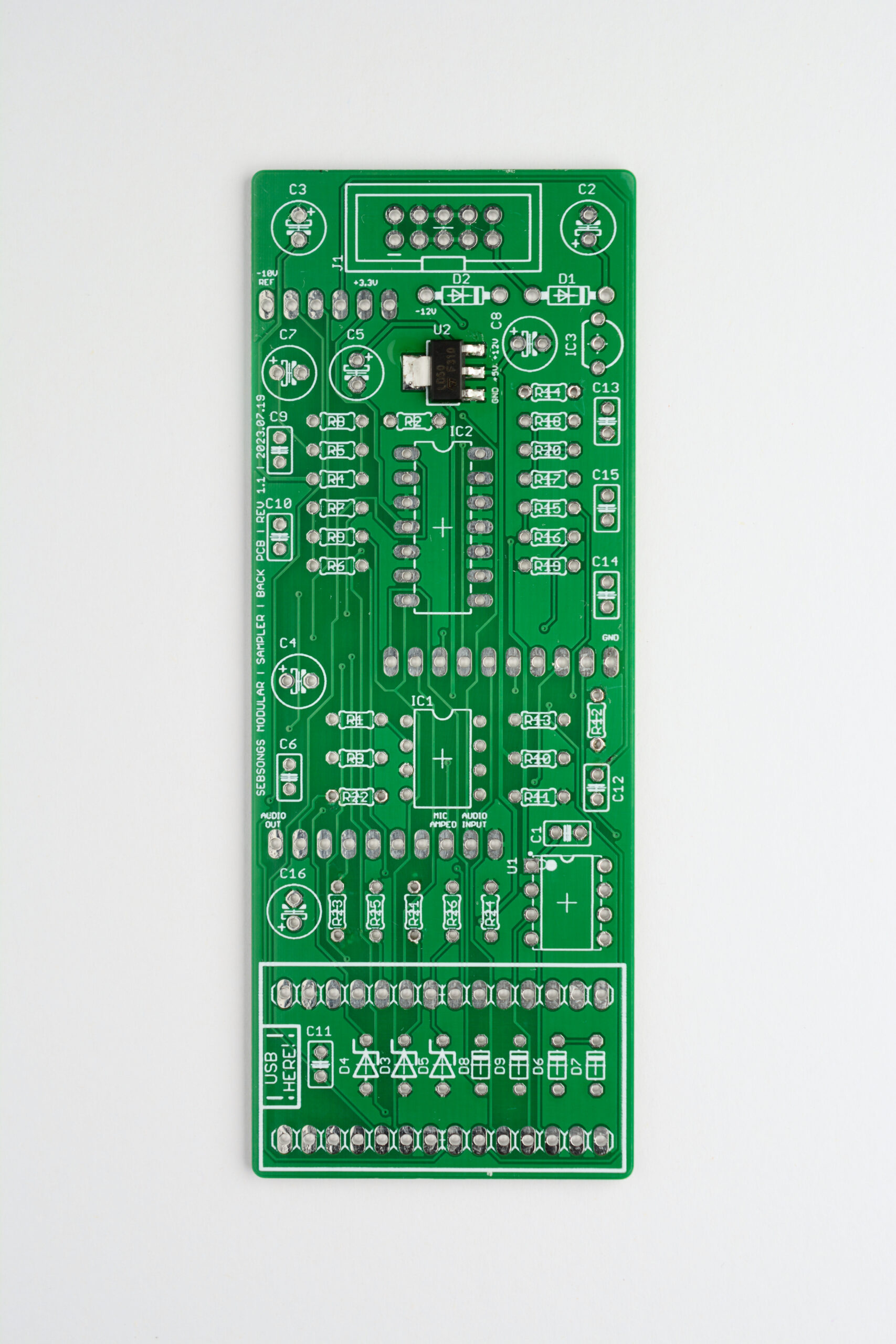
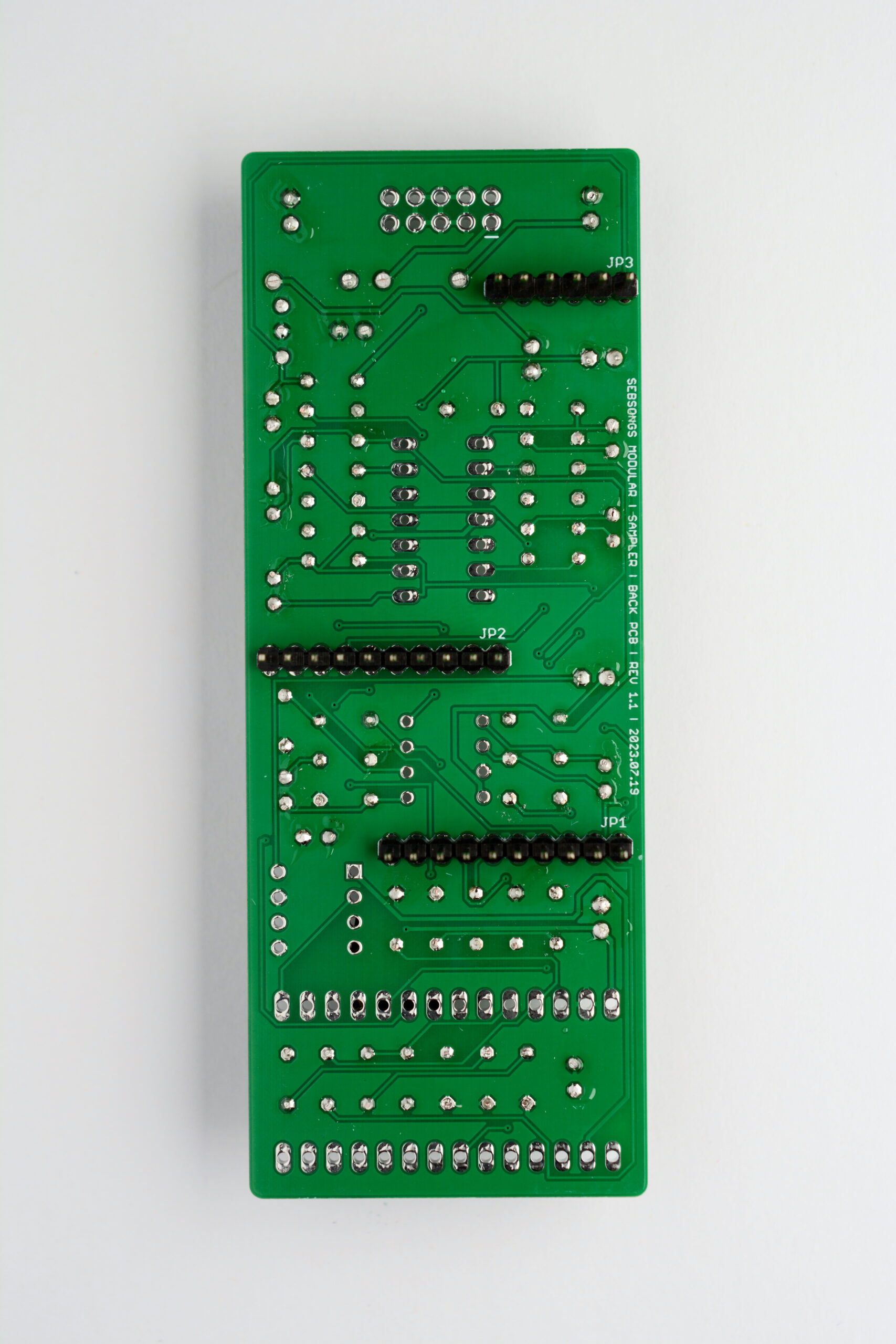
BACK PCB
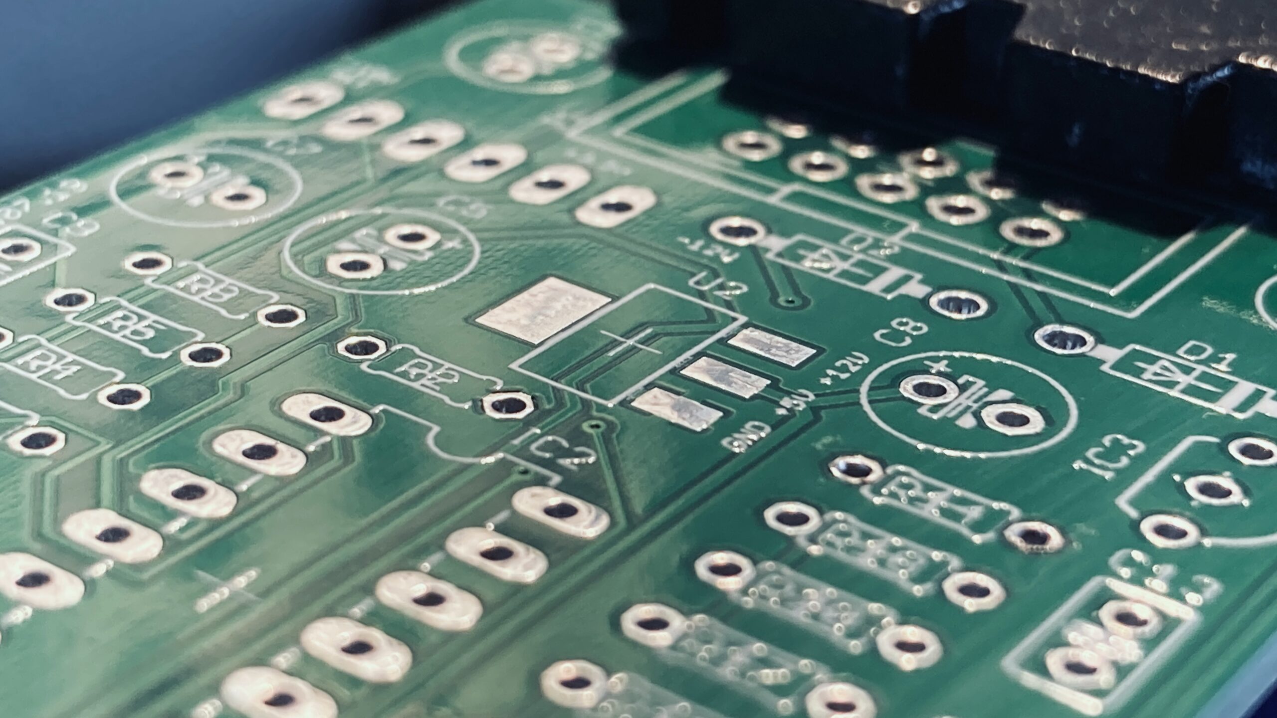
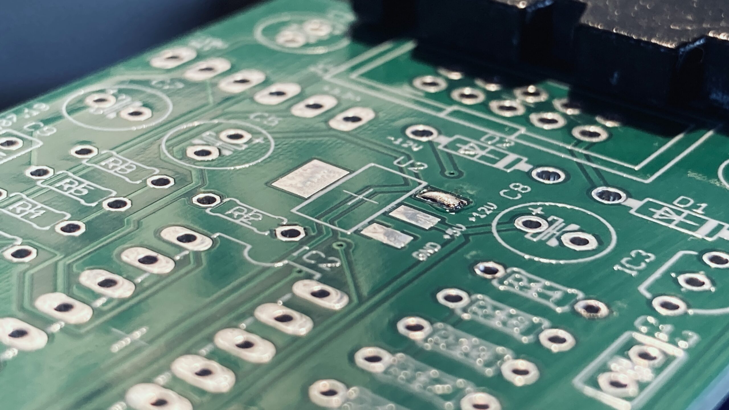
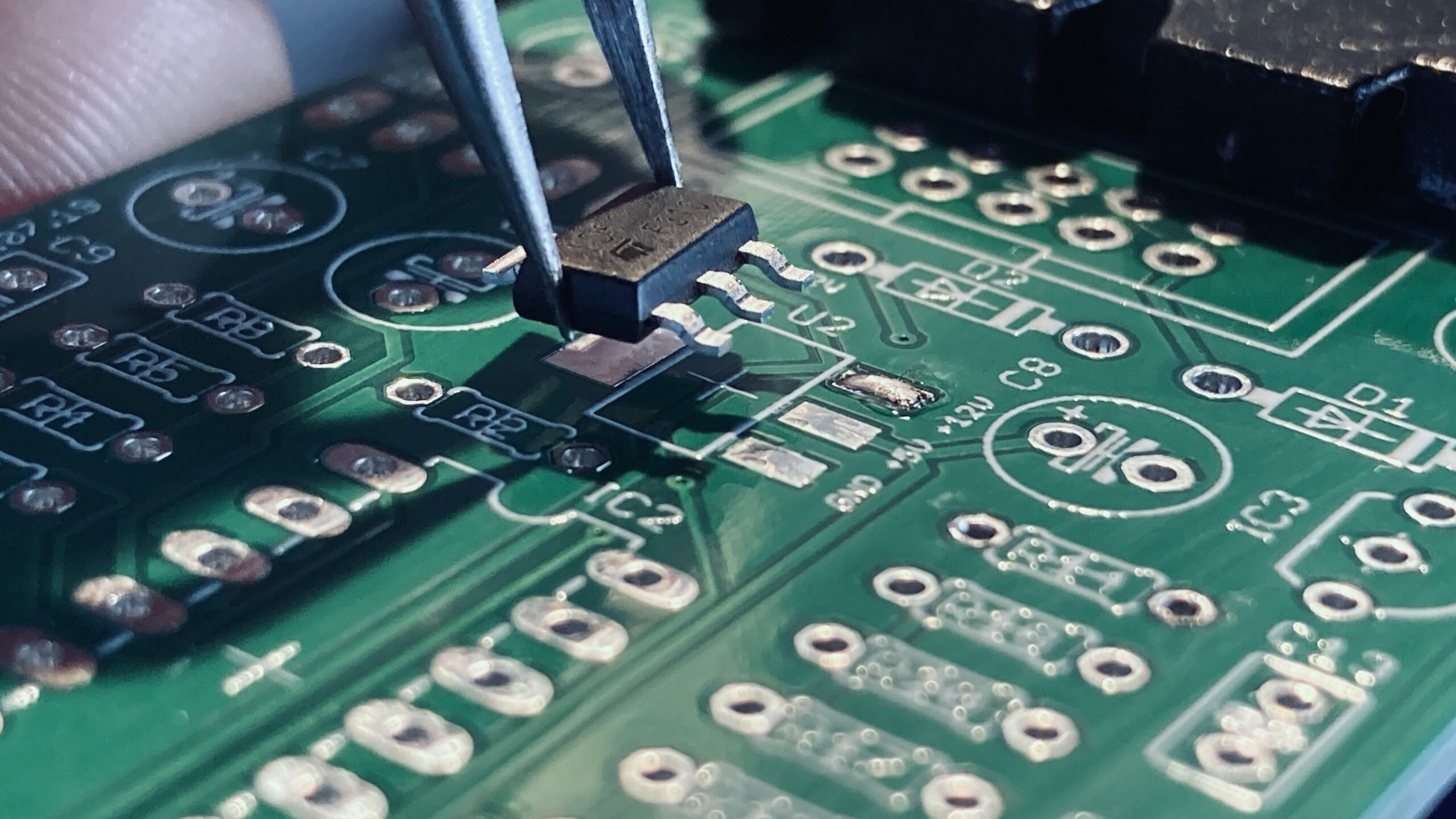
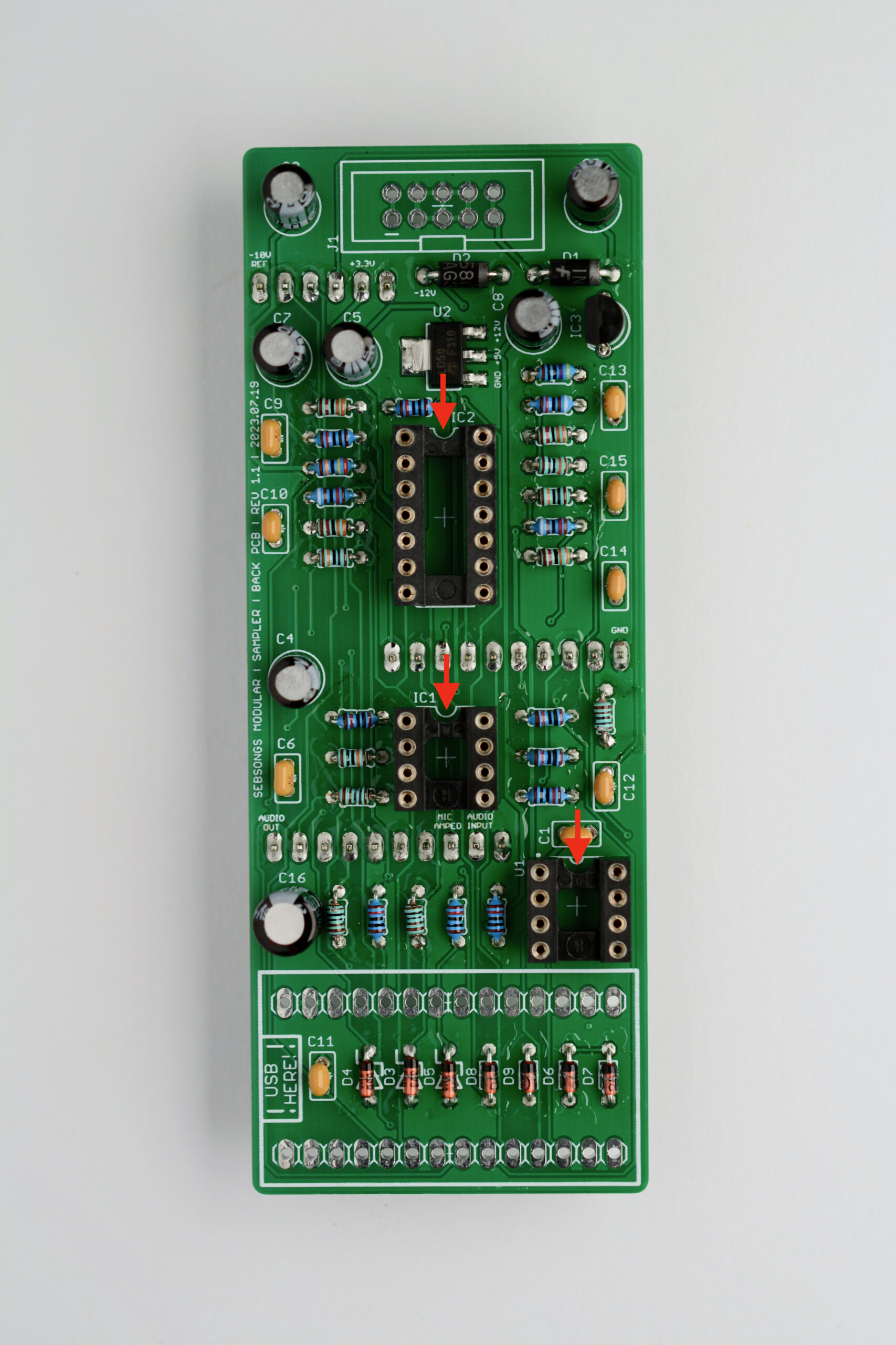
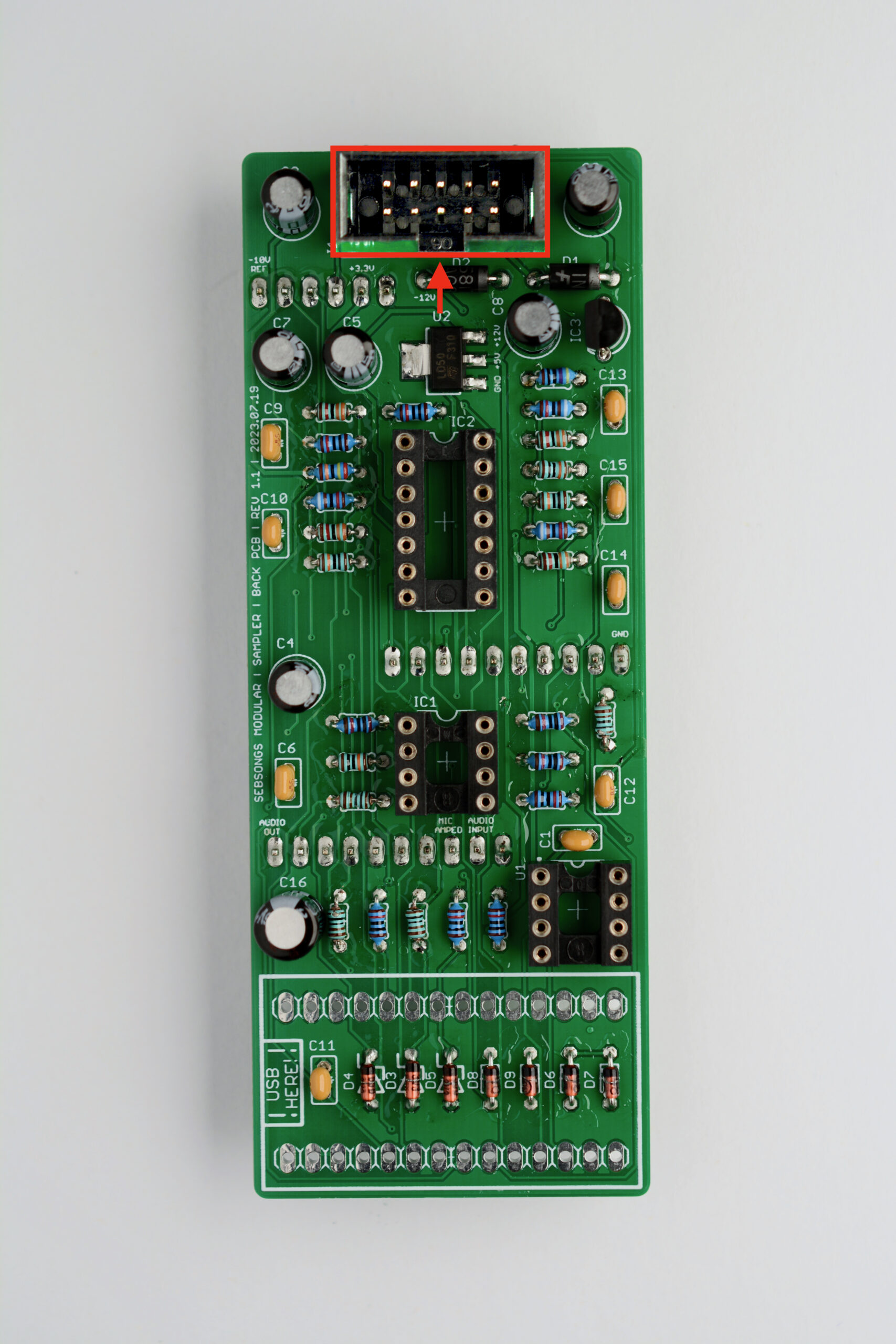
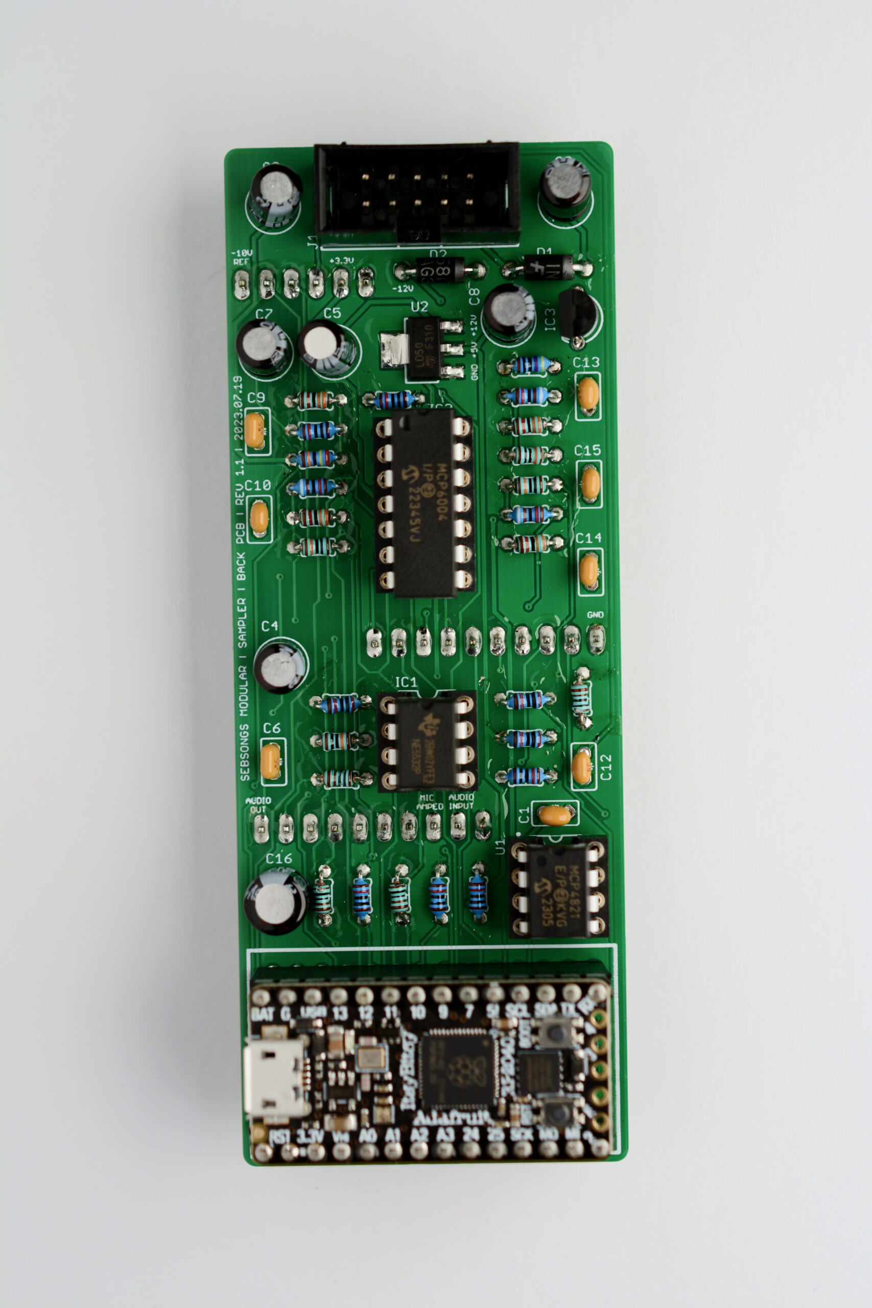
1. SMD Voltage Regulator
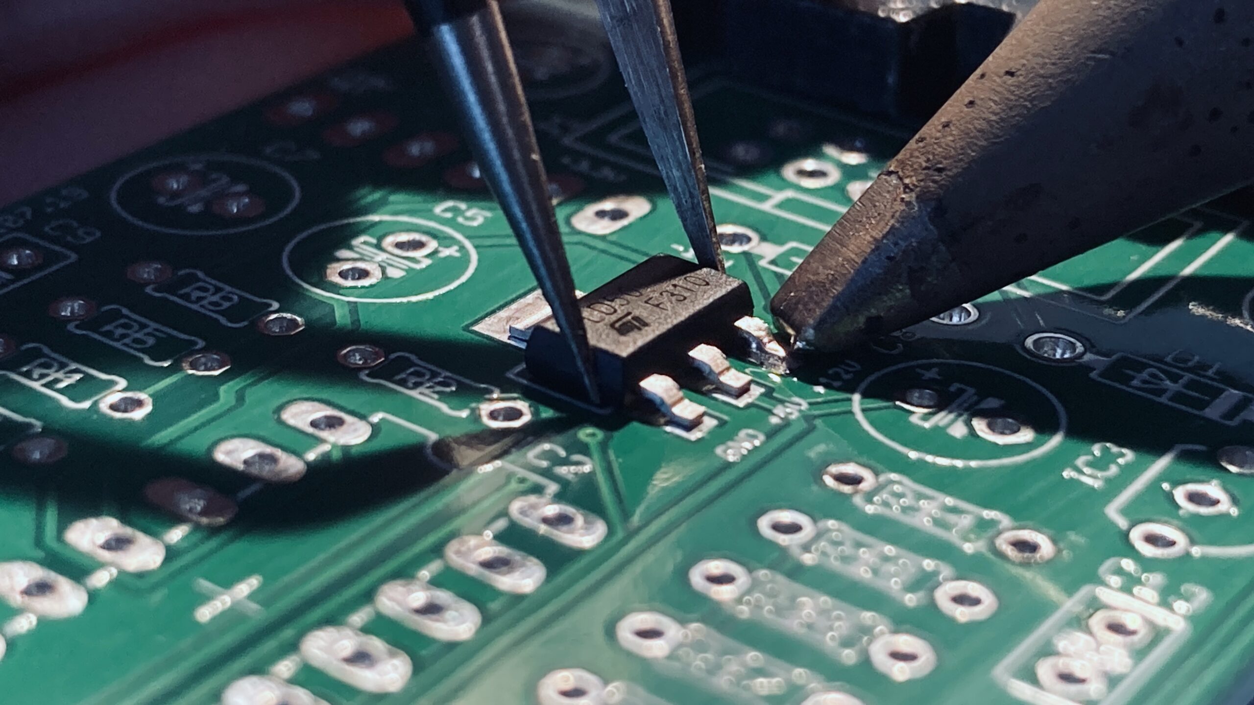
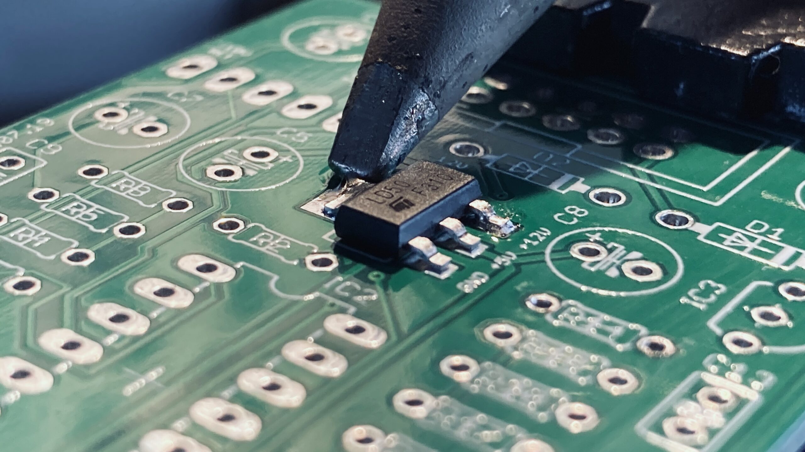
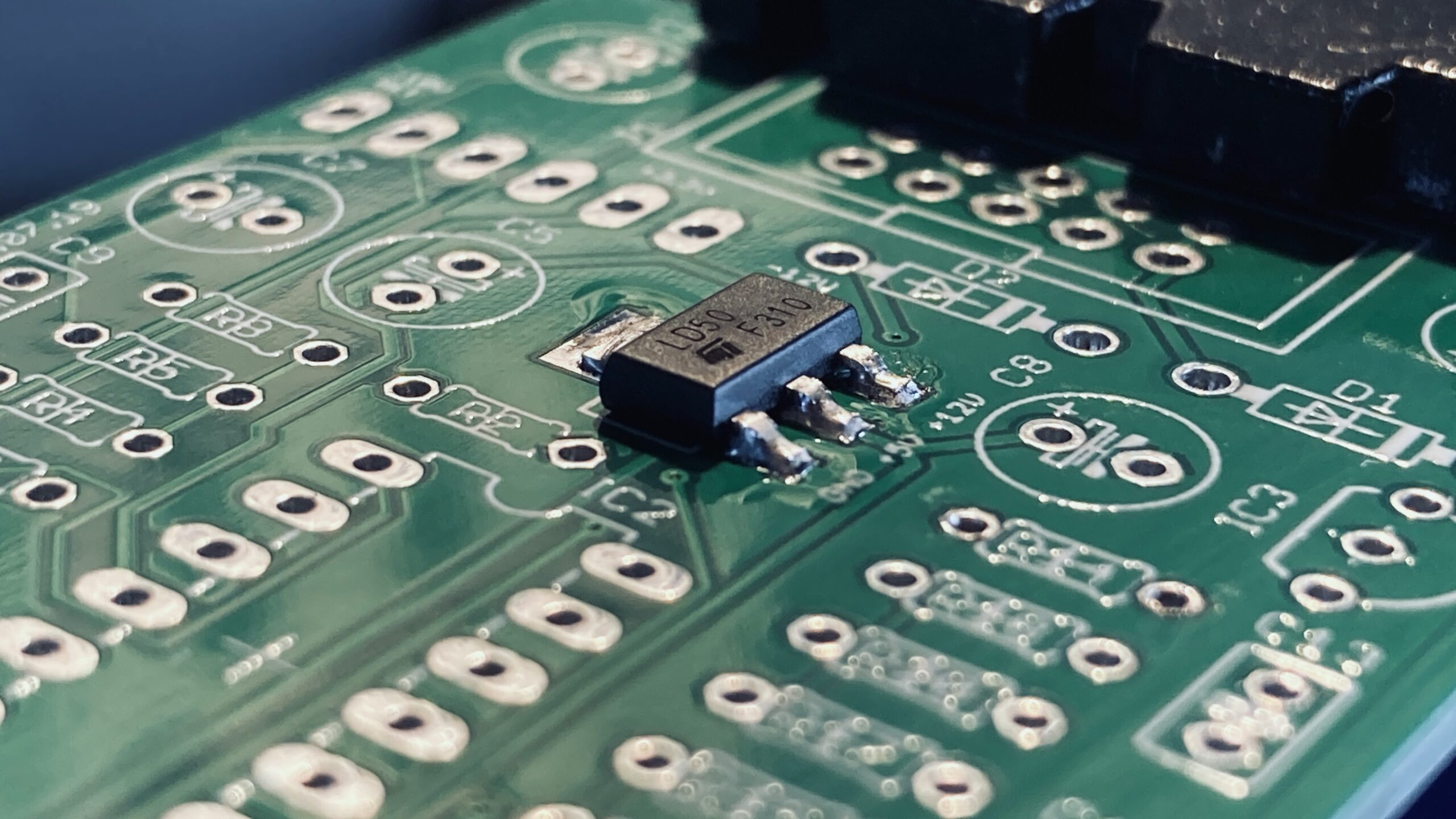
Begin by soldering the surface mount voltage regulator (U2). See detailed instructions below for a step by step guide if you are not used to surface mount soldering. Don’t worry about it too much, it is easy!
Locate the solder pads for component U2.Add a very small amount of solder to one of the three smaller pads.With the angled tweezers, carefully align the voltage regulator on top of the pads.Hold the voltage regulator in place and heat the solder that you placed on the pad before. When the solder has melted, remove the soldering iron and hold the component in place until the solder has cooled.Continue by soldering the large pad on the opposite side.And finally solder the other two smaller pads.
2. Resistors
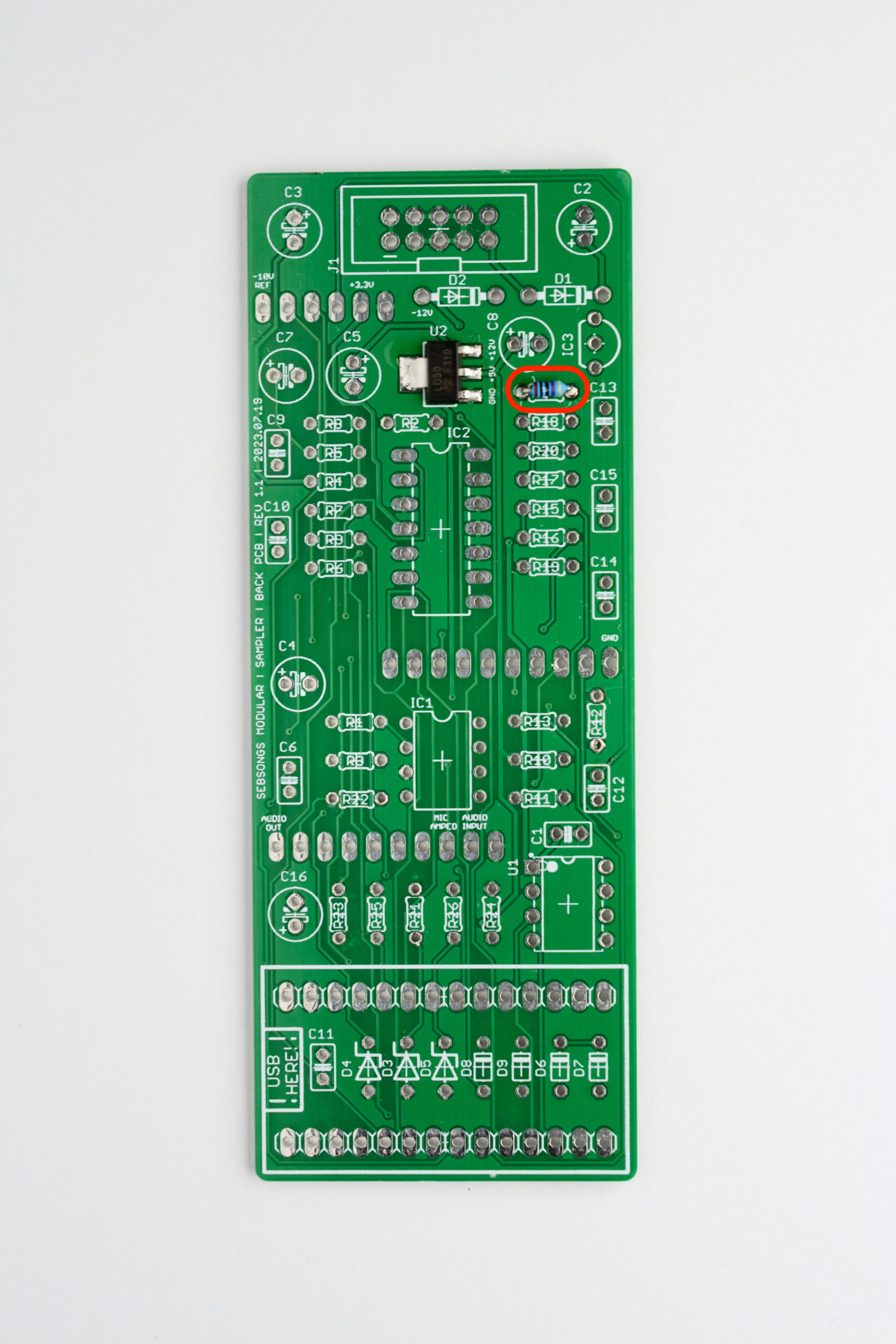
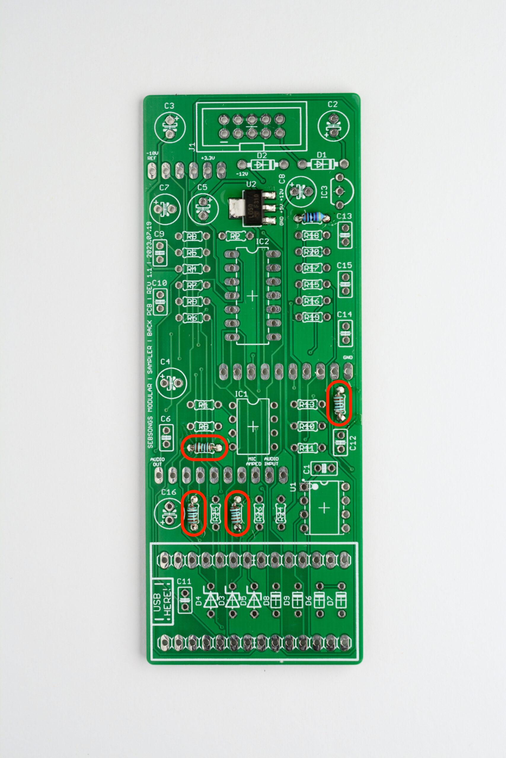
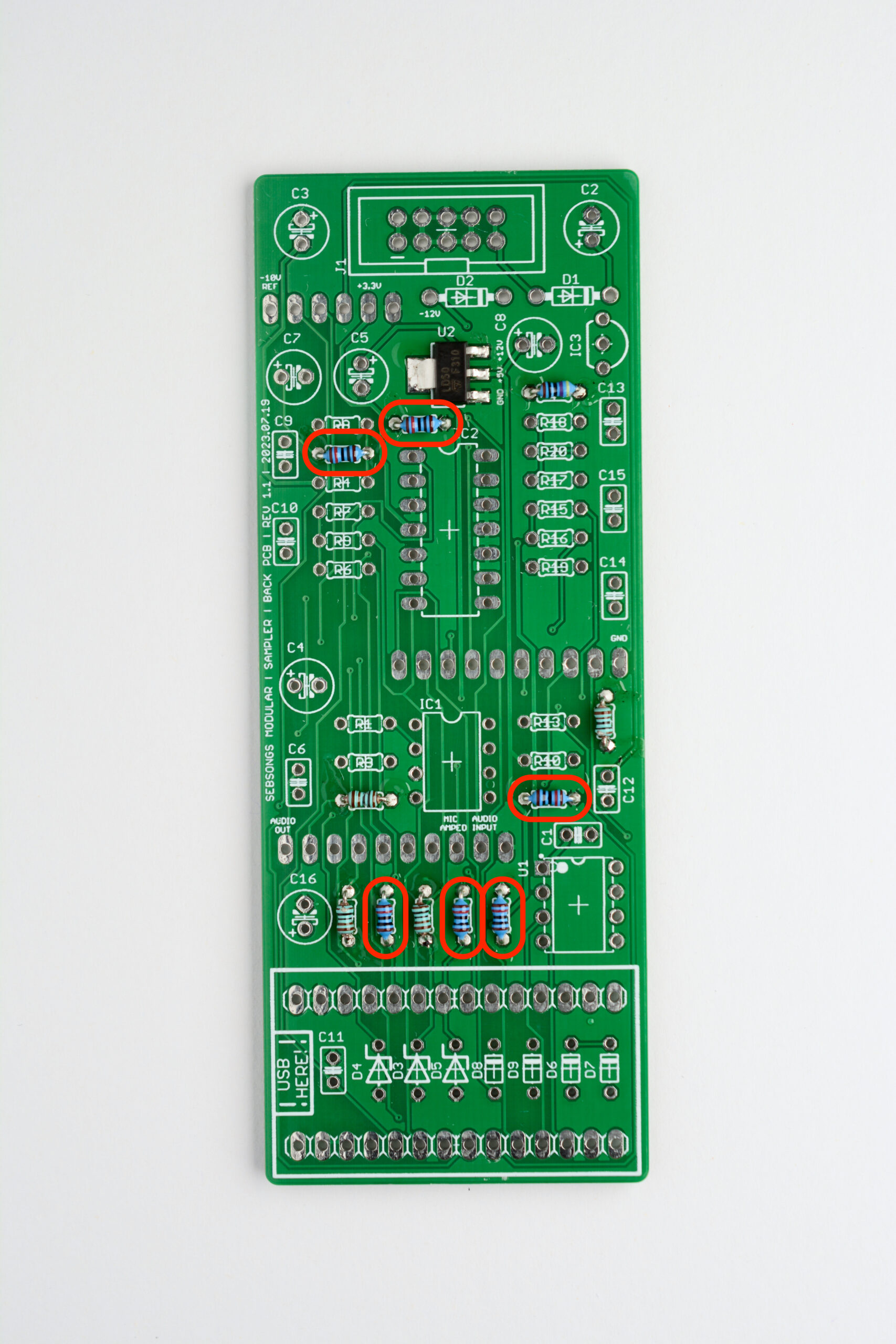
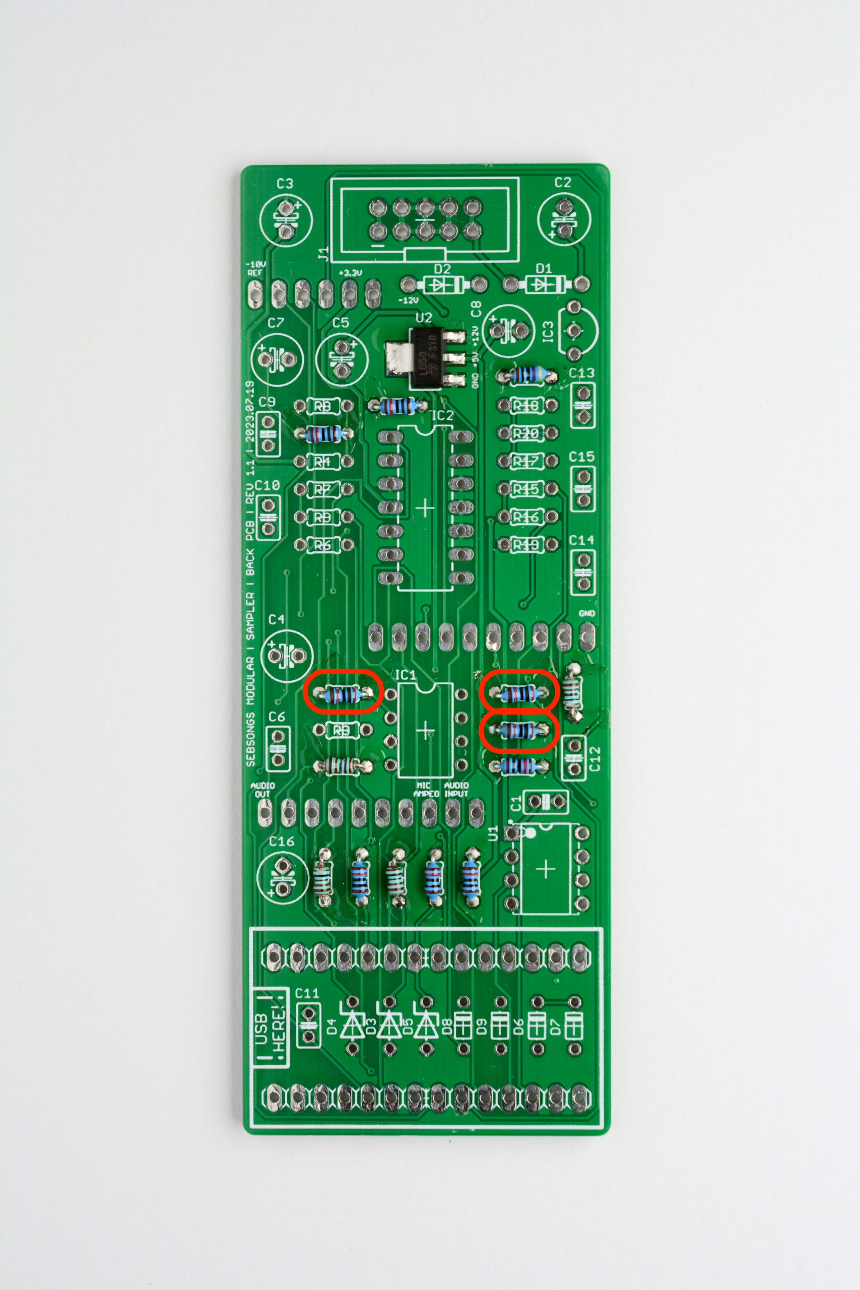
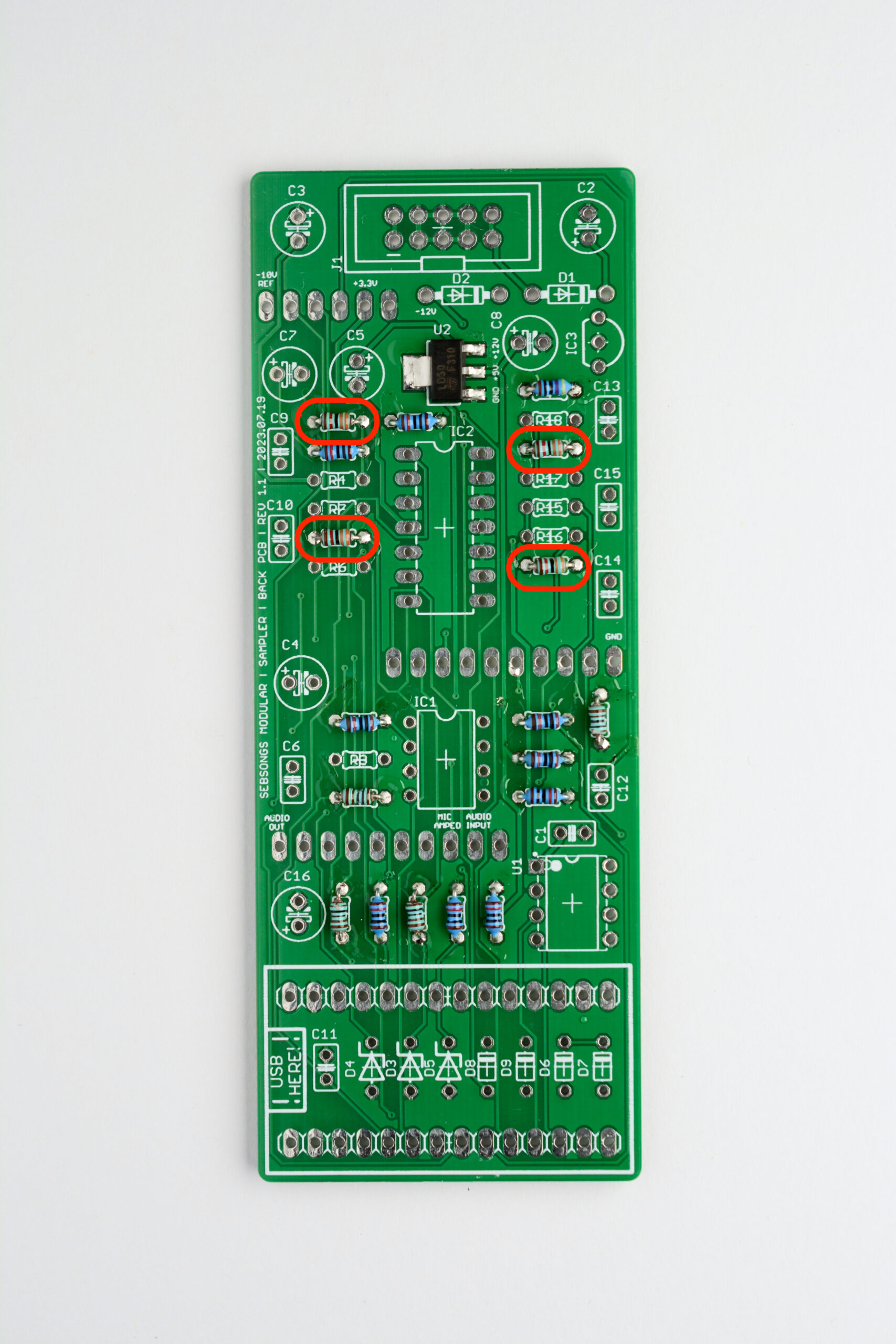
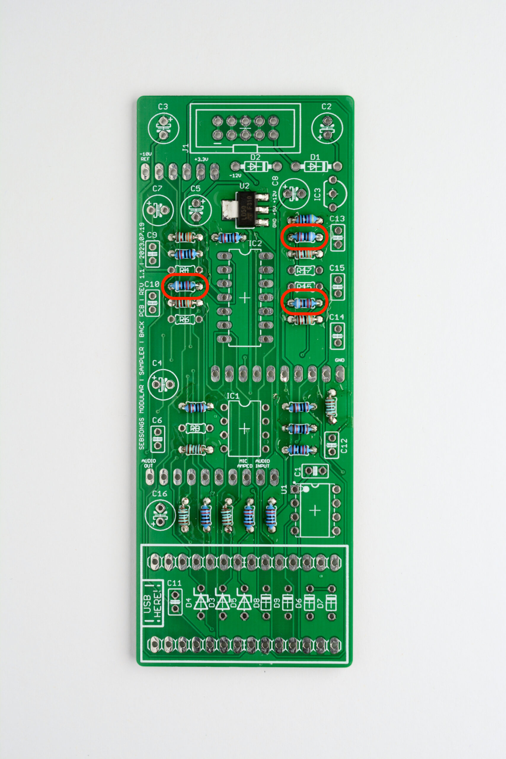
Solder the 470R resistor (R14). See image for placement reference. Bend the legs by hand as close to the resistor body as possible to get a good fit on the PCB. This applies to all resistors going forward.Solder the 1K resistors (R12, R21, R22, R23). See image for placement reference. Solder the 10K resistors (R2, R5, R11, R24, R25, R26). See image for placement reference. Solder the 20K resistors (R1, R10, R13). See image for placement reference. Solder the 33K resistors (R8, R9, R19, R20). See image for placement reference. Solder the 91K resistors (R7, R16, R18). See image for placement reference. Solder the 100K resistors (R3, R6, R15, R17). See image for placement reference. Solder the 240K resistor (R4). See image for placement reference.
2. Capacitors
NOTE: Before soldering the capacitors, you might want to go ahead and solder the IC sockets (IC1, IC2 & U1) and power header (J1) in step 5, as some it might be slightly awkward to hold them in properly when the electrolytic capacitors have been fitted.
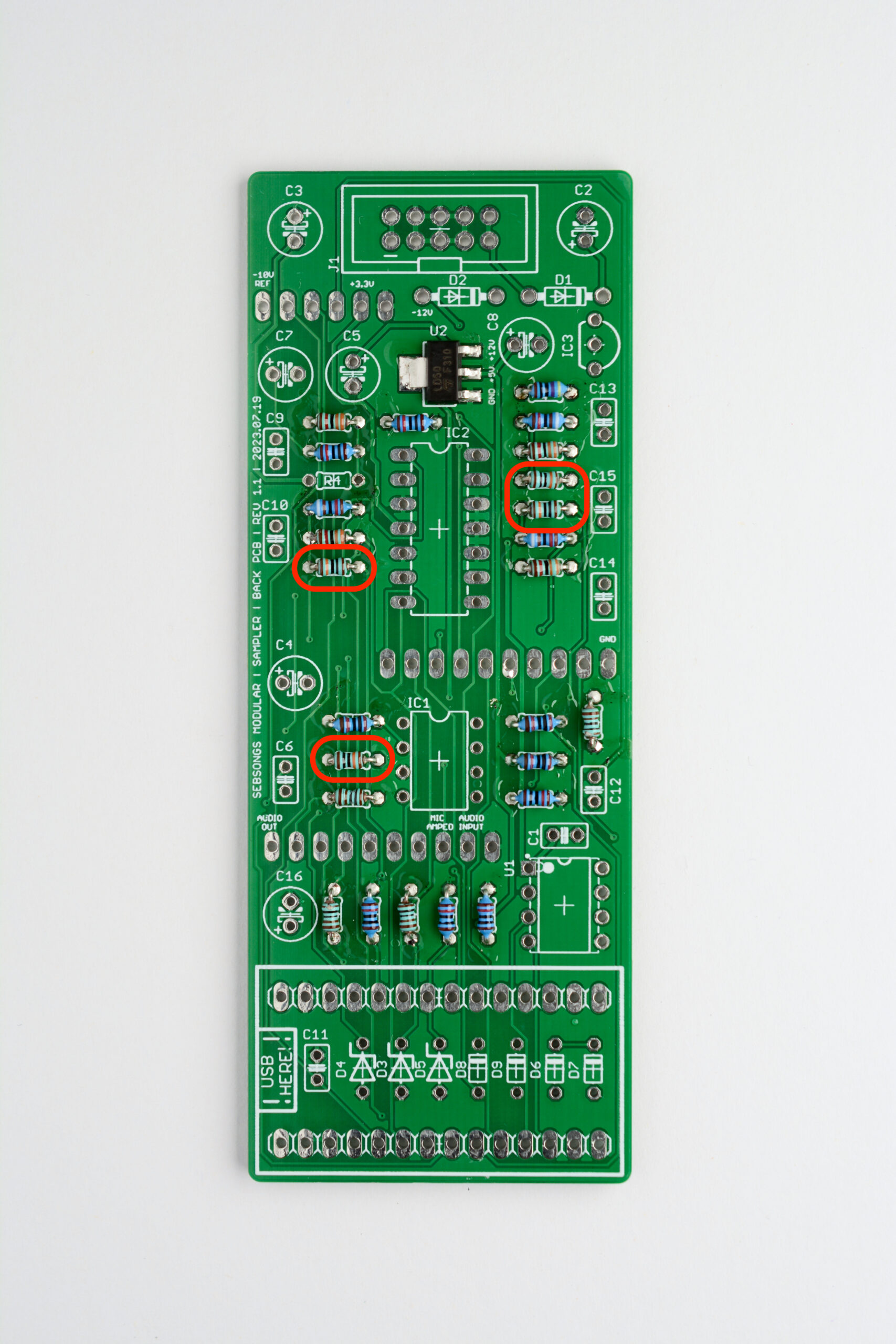
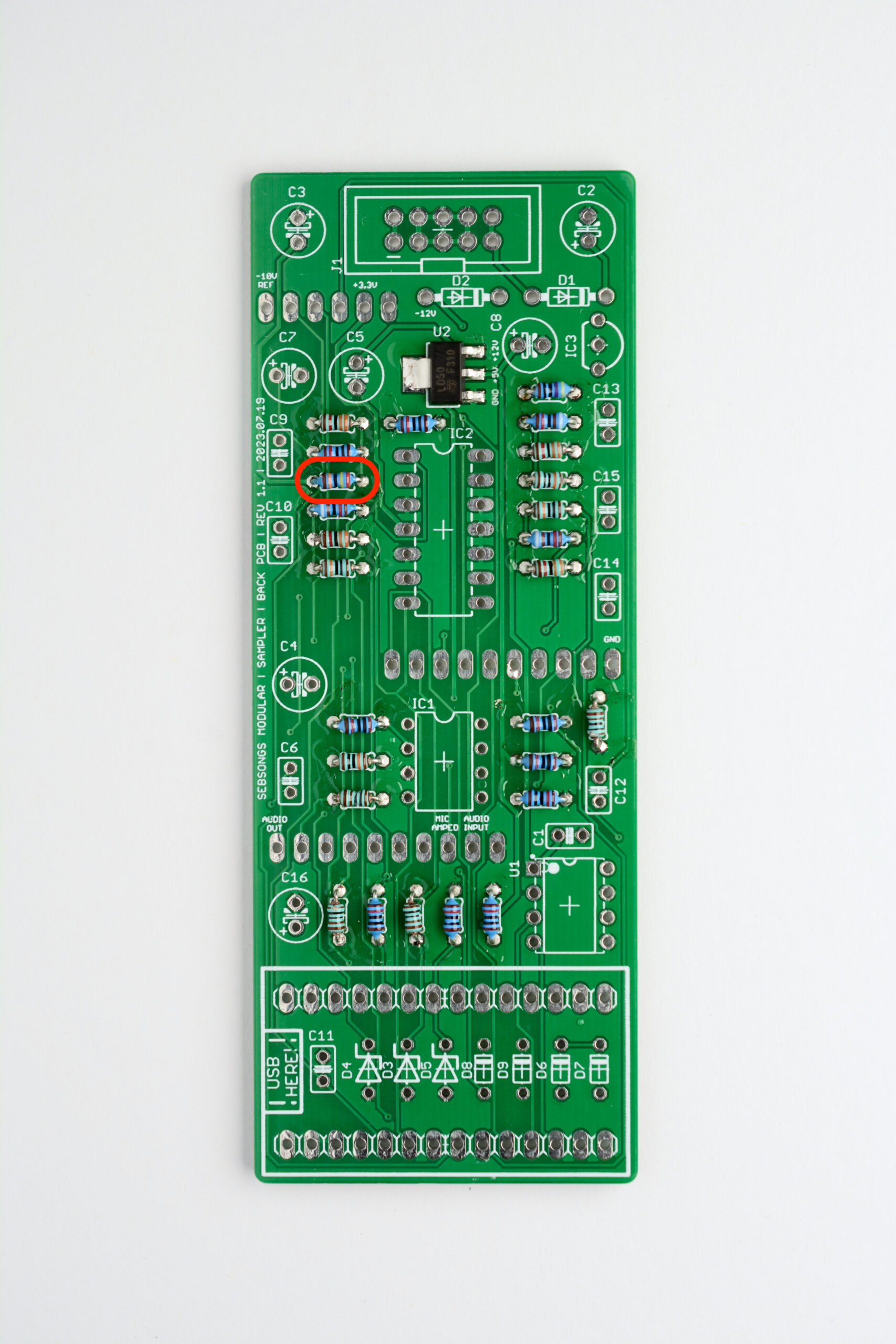
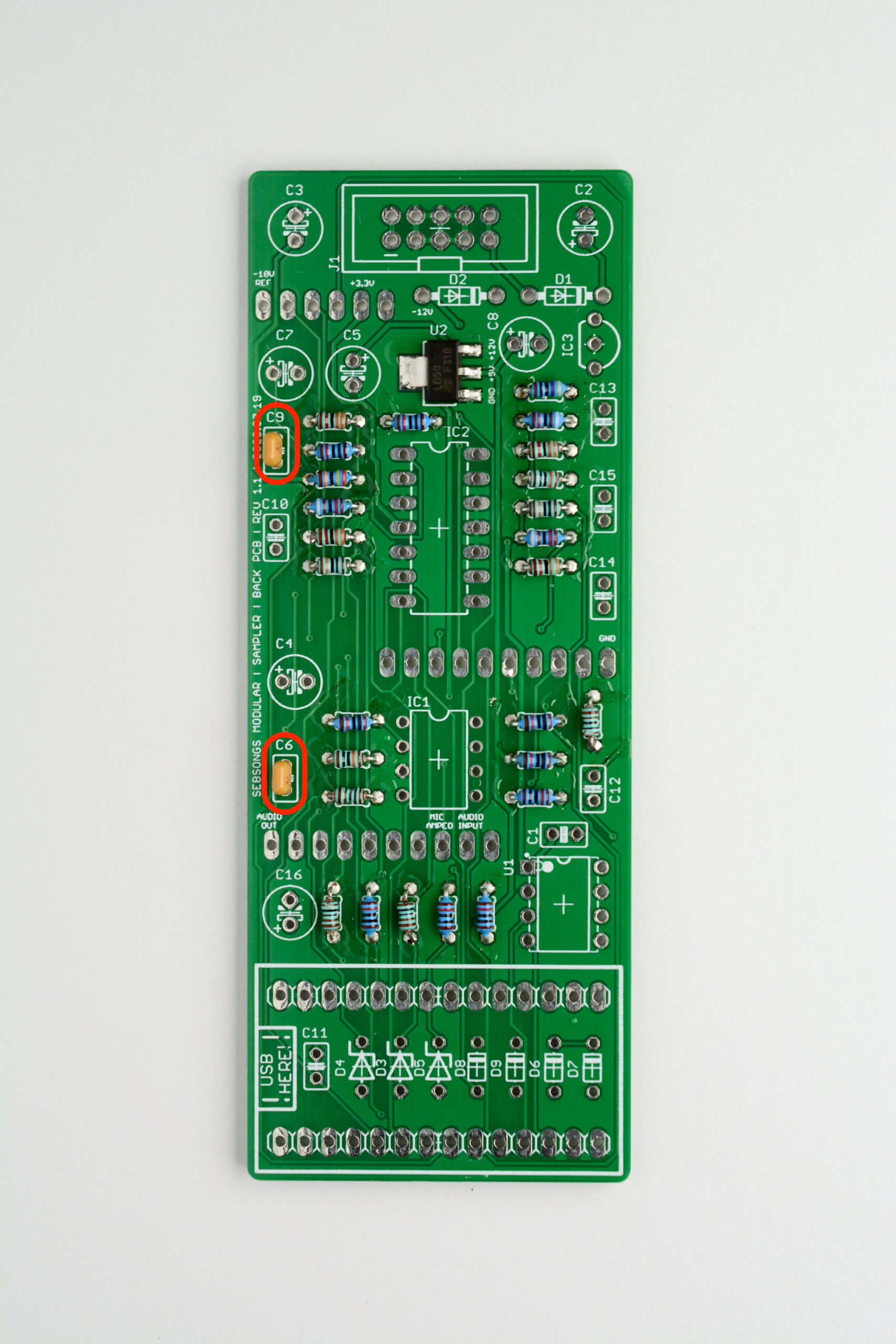
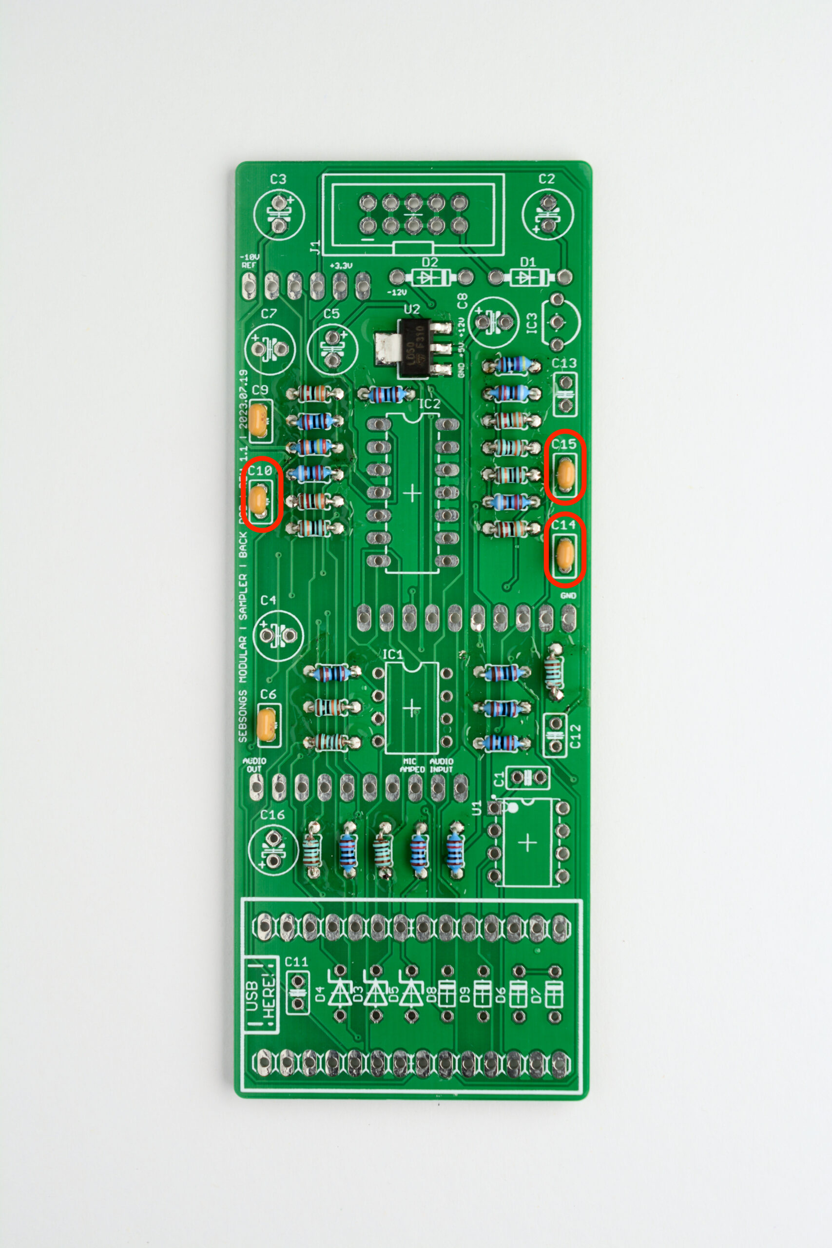
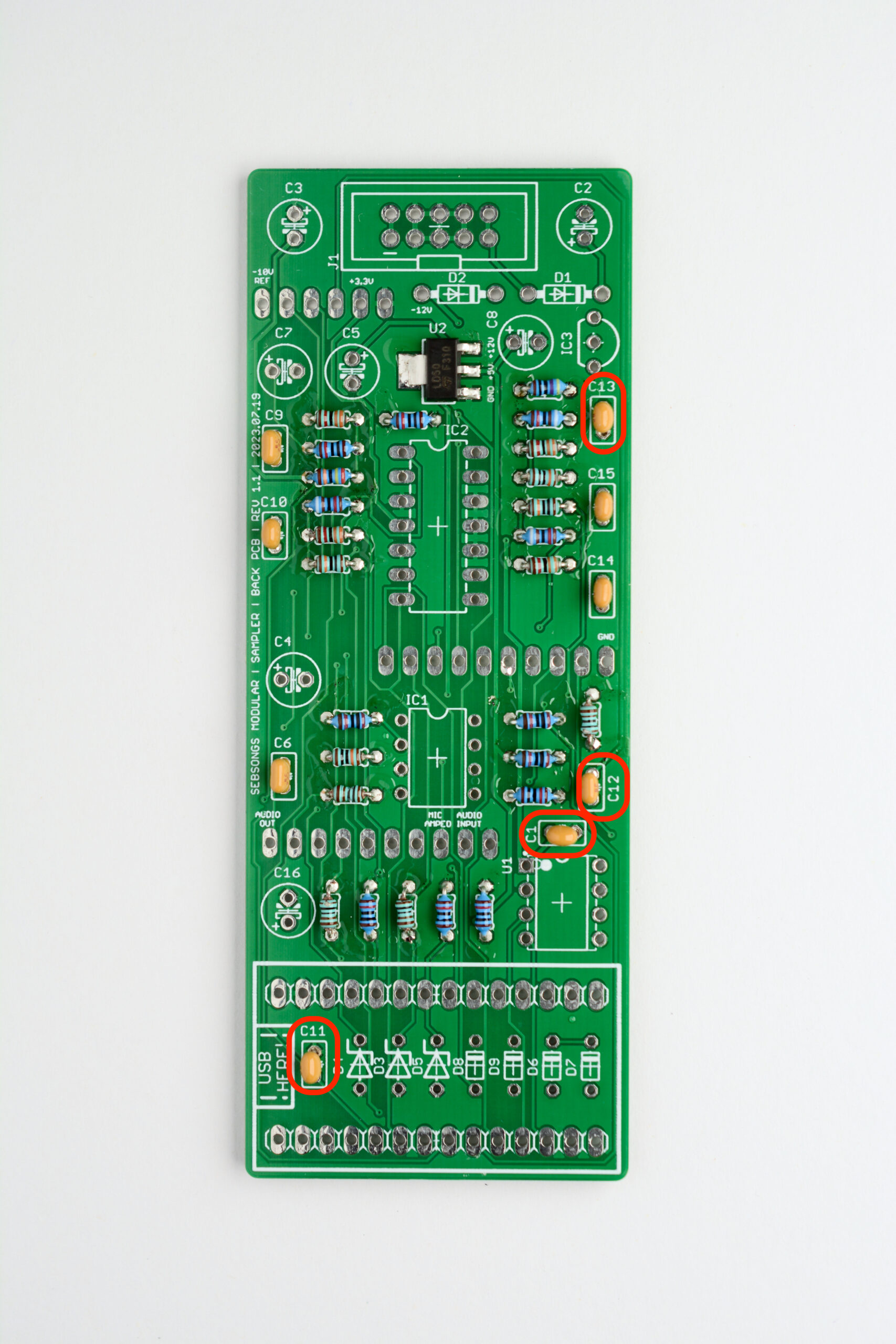
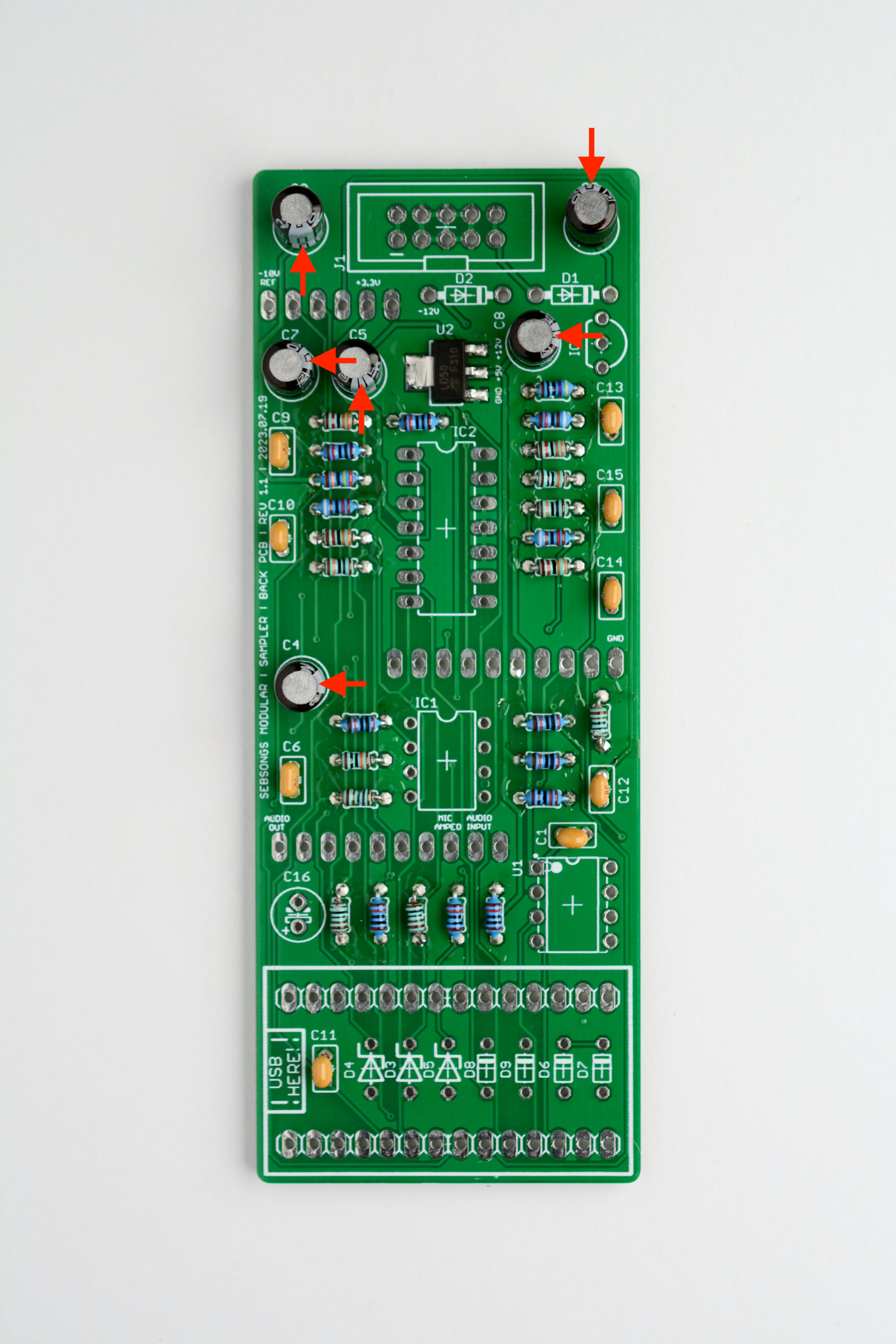
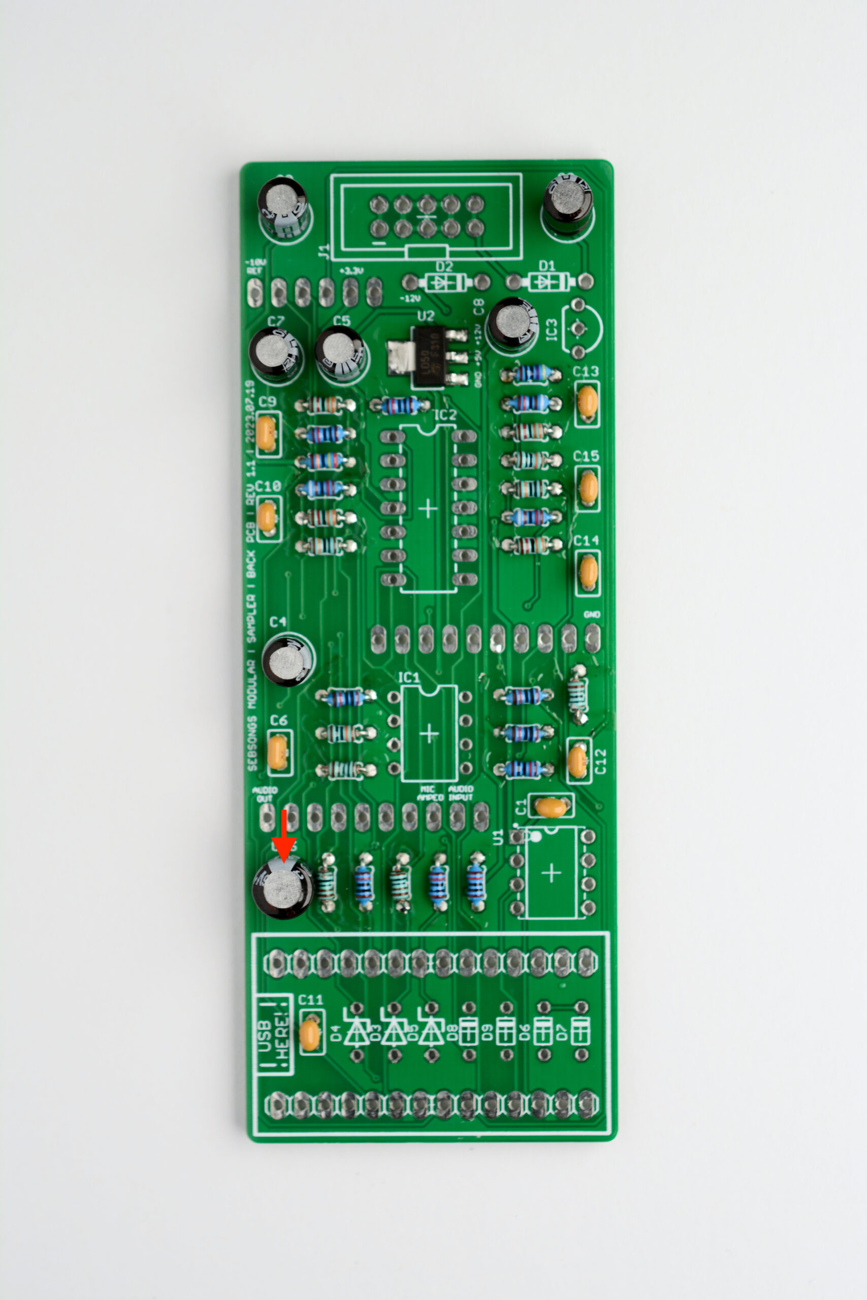
Solder the 22pF [22J] ceramic capacitors (C6, C9). See image for placement reference. Solder the 1nF [102] ceramic capacitors (C10, C14, C15). See image for placement reference. Solder the 100nF [104] ceramic capacitors (C1, C11, C12, C13). See image for placement reference. Solder the 10uF electrolytic capacitors (C2, C3, C4, C5, C7, C8). Make sure to check the polarity twice before soldering! See image for placement reference. Solder the 100uF electrolytic capacitor (C16). Make sure to check the polarity twice before soldering! See image for placement reference.
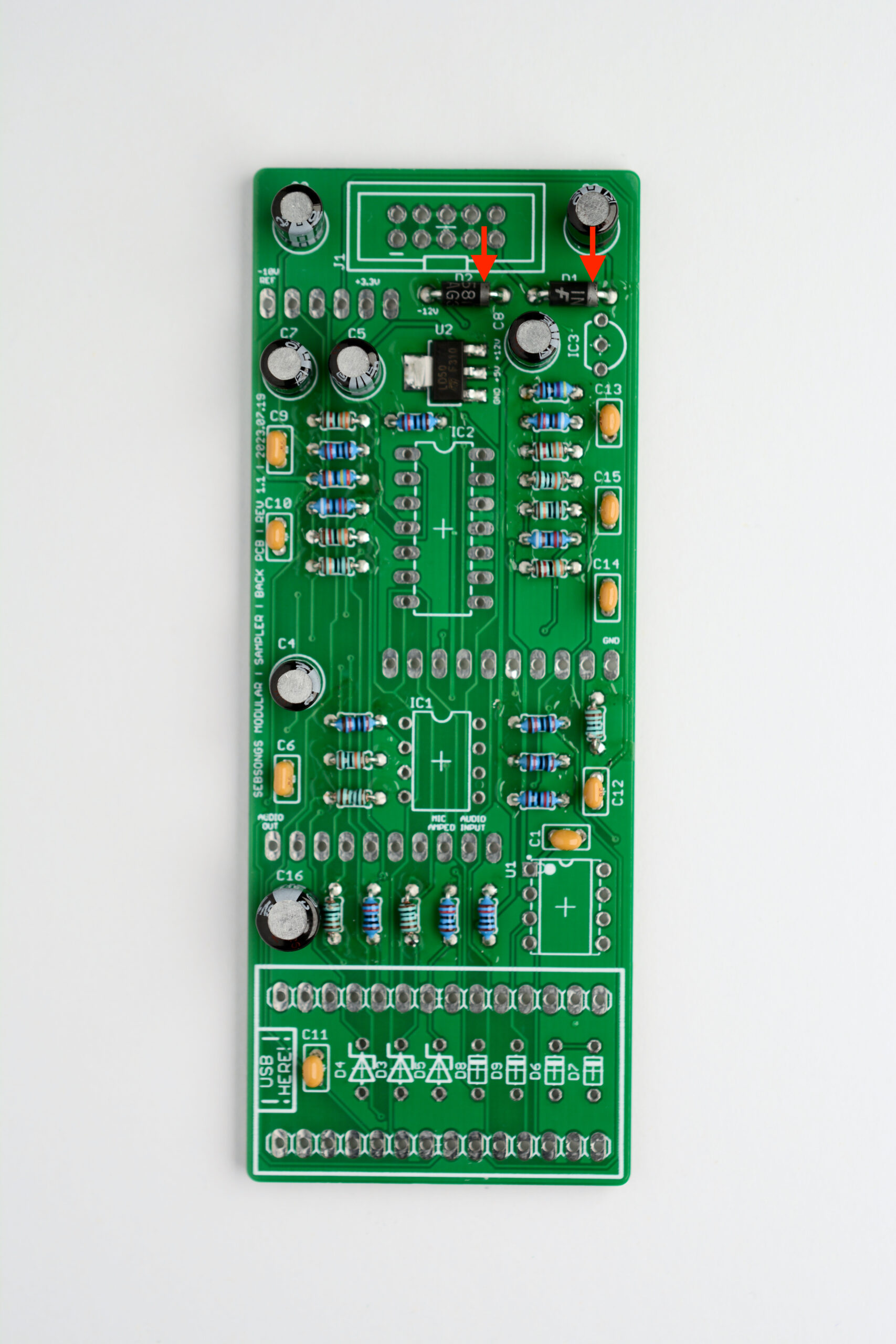
3. Diodes
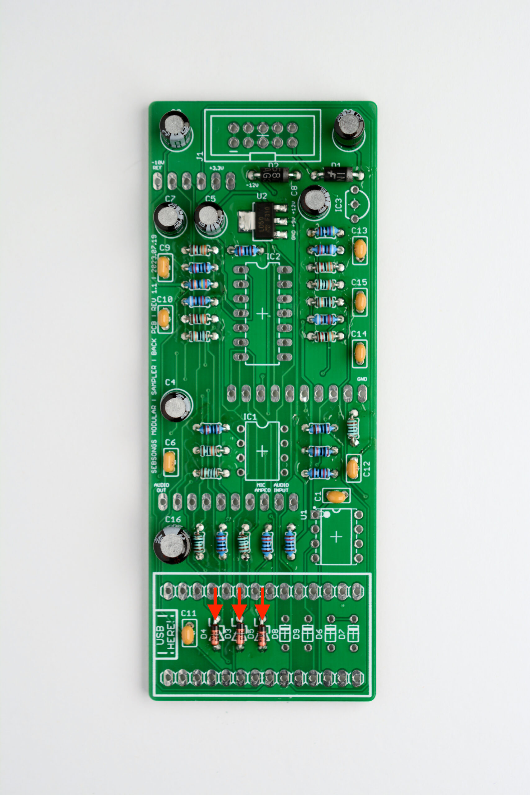
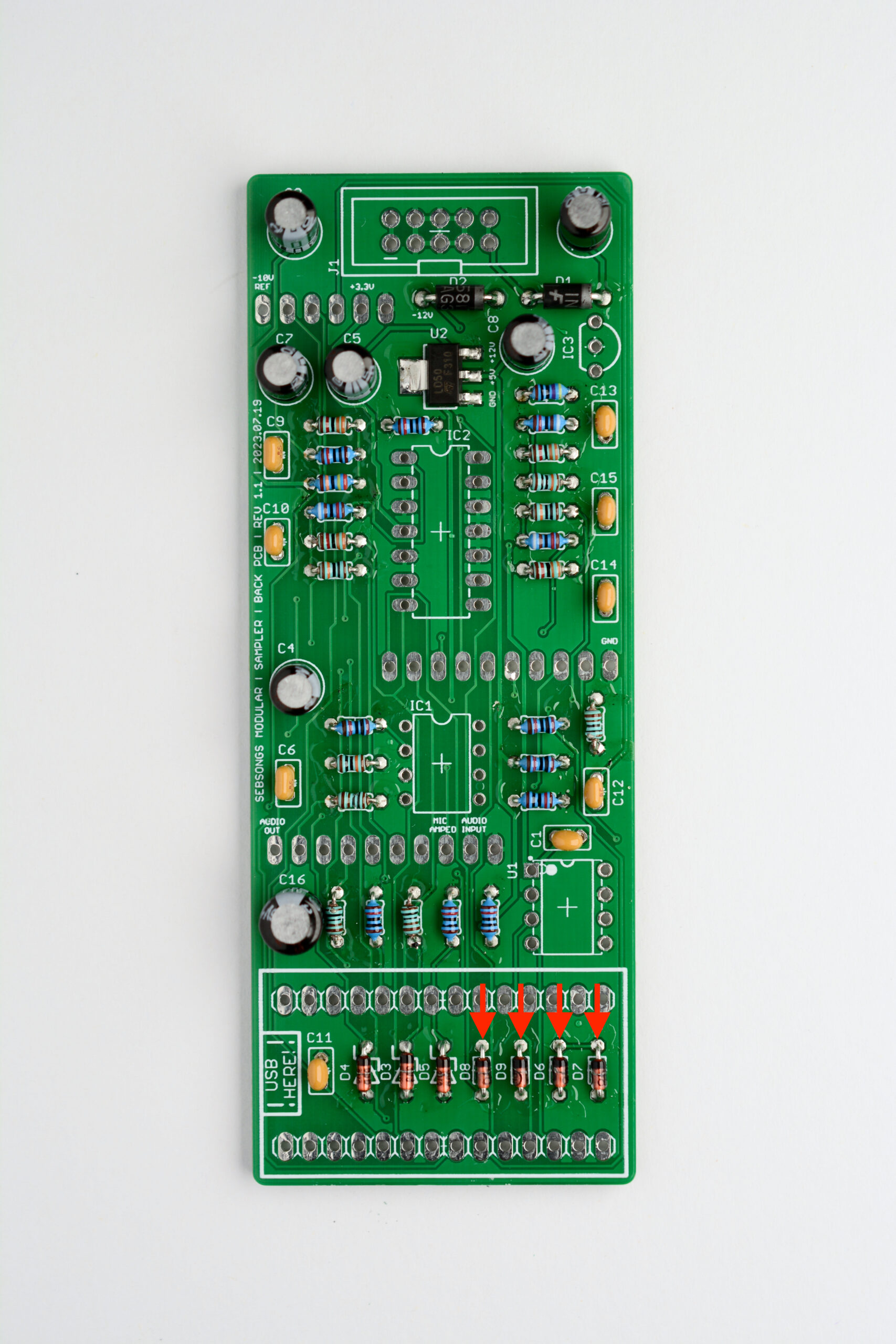
Solder the 1N5817 schottky diodes (D1, D2). Make sure to check the polarity twice before soldering! See image for reference.Solder the 3,3V zener diodes (D3, D4, D5). Make sure to check the polarity twice before soldering! See image for reference.Solder the 1N4148 diodes (D6, D7, D8, D9). Make sure to check the polarity twice before soldering! See image for reference.
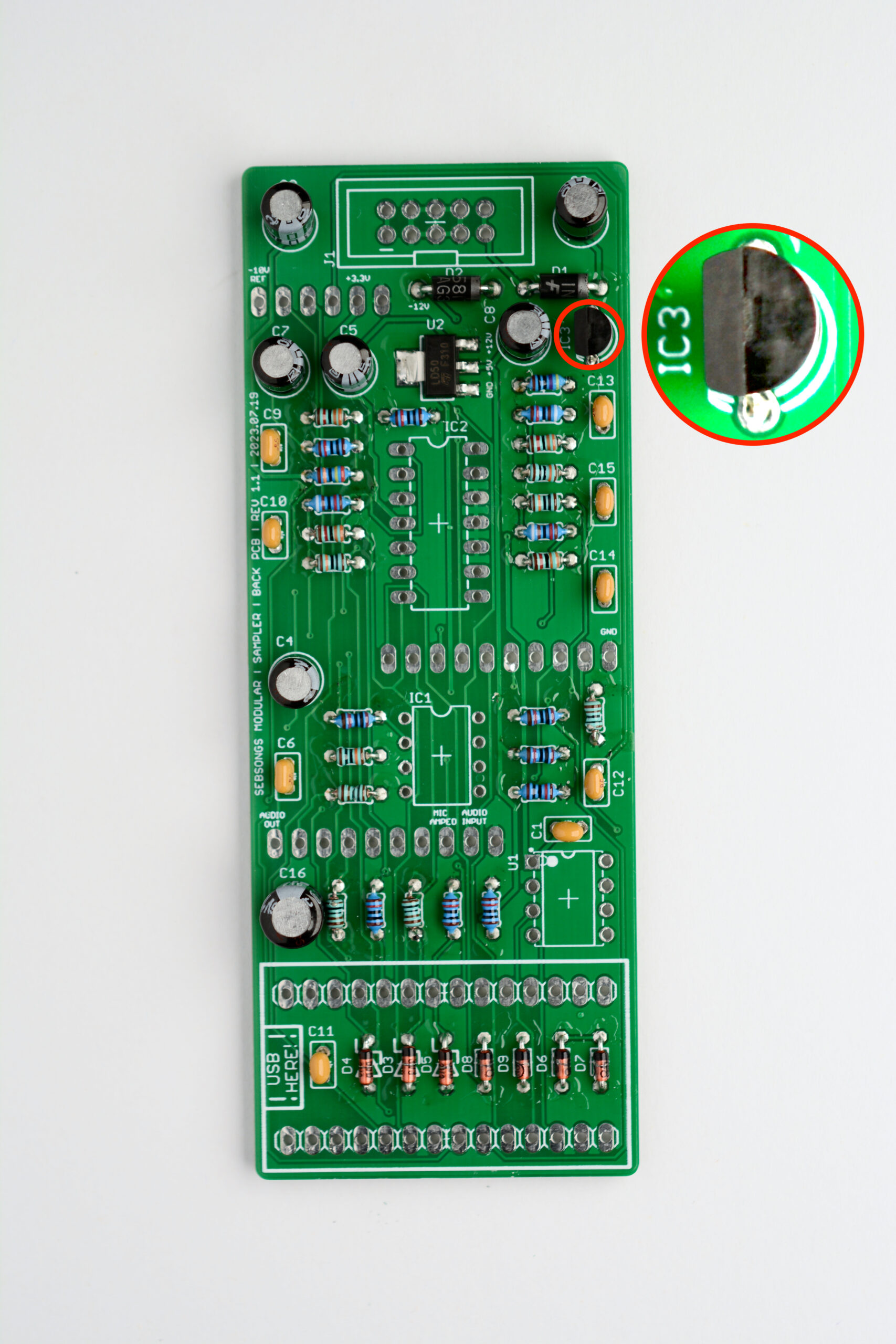
4. Voltage Reference
Solder the LM4040 voltage reference (IC3). Make sure to check the orientation of the component twice before soldering! See image for reference.
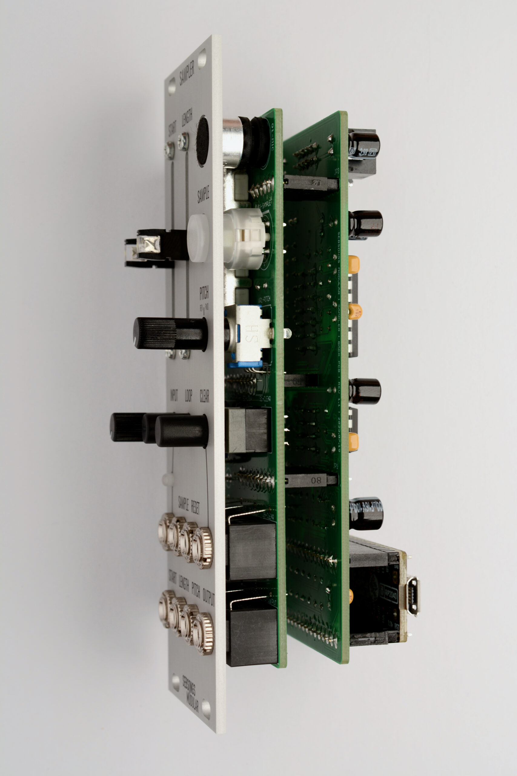
5. Headers and sockets
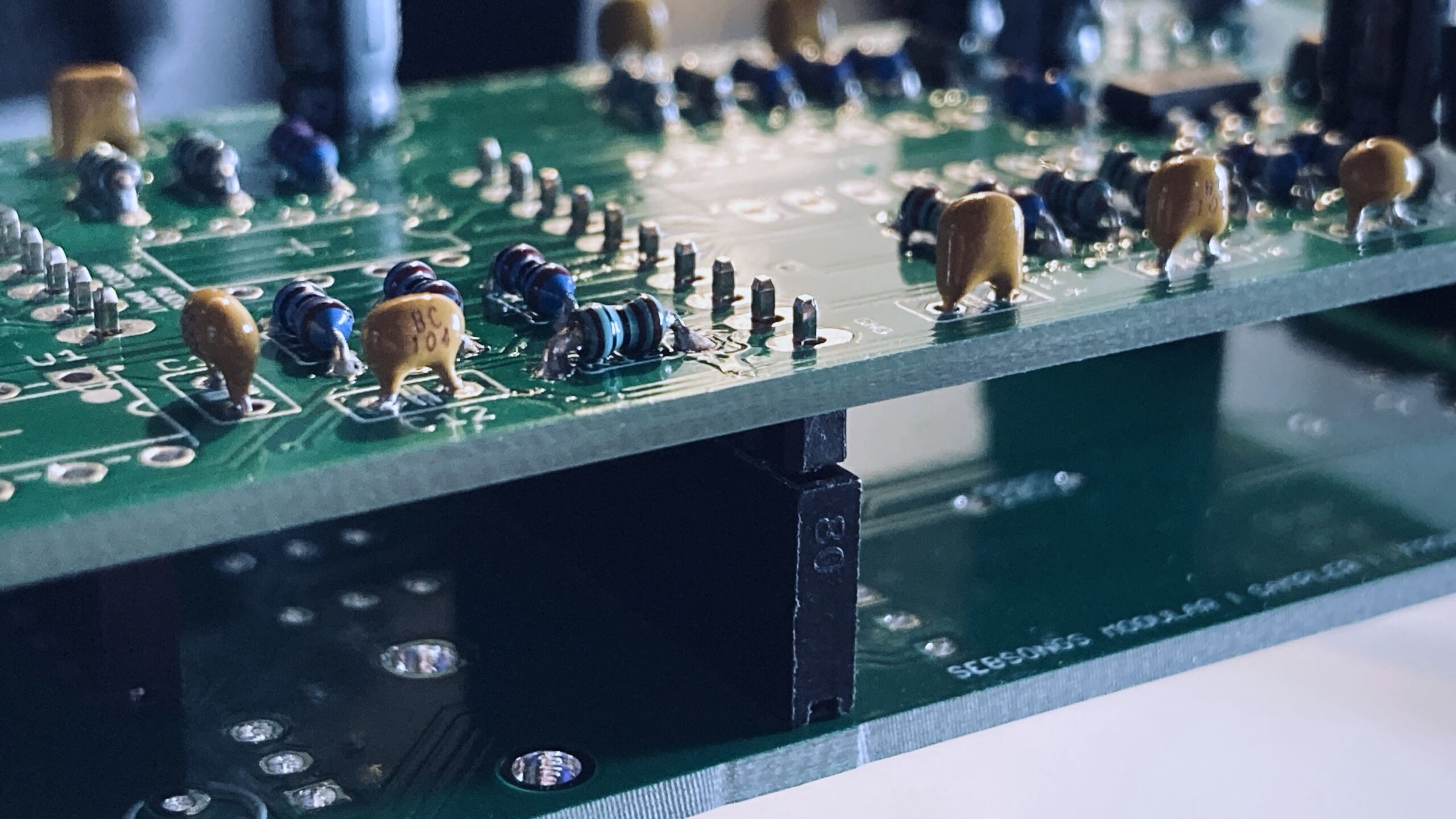
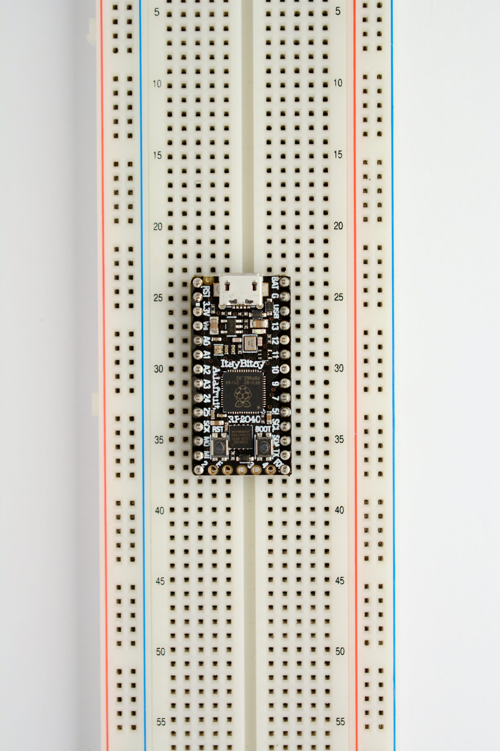
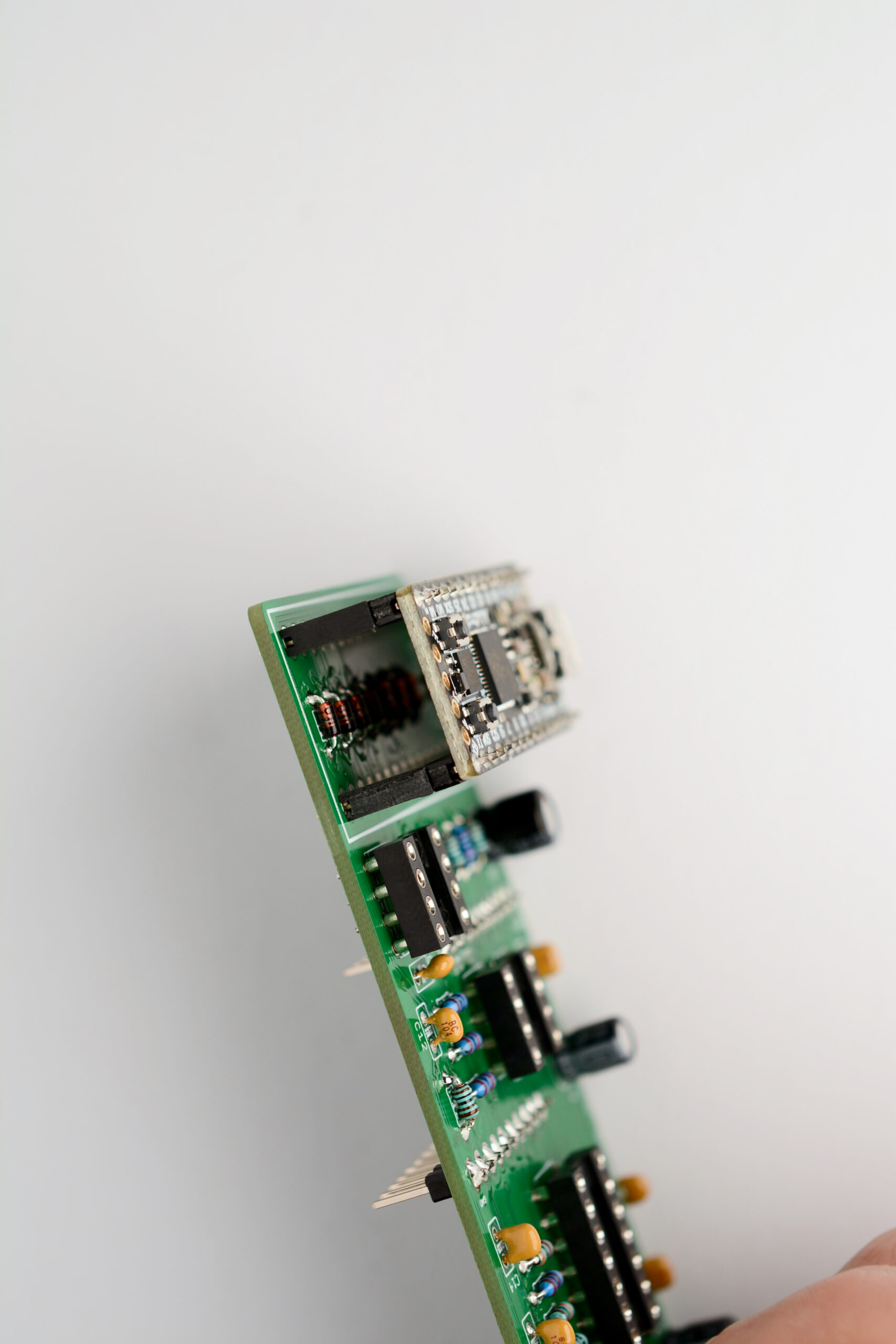
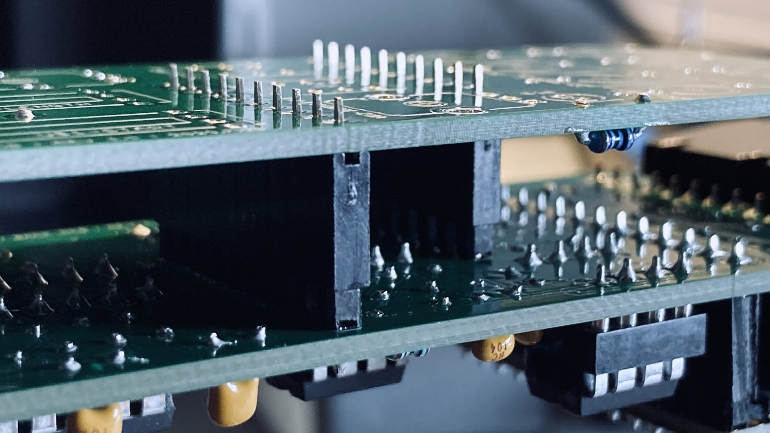
Connect the 10 and 6 pin recepticles and pin headers to each other and place them on the FRONT PCB with the pin headers oriented up. Carefully place the BACK PCB on top and align the two PCBs as showed in the image above. Solder one pin on each pin header while taking care to keep the PCBs aligned. Check alignment again and then solder the rest of the pins.You should now have the pin headers solder nice and straigth onto the back of the BACK PCB, as showed in the image above.Solder the IC sockets (IC1, IC2, U1). Keep in mind the orientation of the IC sockets.Solder the Eurorack power socket (J1). Keep in mind its orientation! See image for reference.Prepare the pin headers for the Itsybitsy RP2040 by cutting them to size if needed, and fit them in a breadboard. Place the Itsybitsy RP2040 on top and solder all the pins as shown in the image above. Start with two diagonal corner pins to align everything, and then solder the rest.Prepare the pin recepticles for the Itsybitsy RP2040 by cutting them to size if needed, and fit them on the pin headers of the Itsybitsy RP2040. Place the full assembly on the BACK PCB as shown in the image above. Again, start soldering two diagonal corner pins to align everything, and then solder the rest.
6. Final assembly of the BACK PCB
Fit the MCP6004 (IC2), NE5532 (IC1) and MCP4821 (U1) ICs in their respective IC sockets. The BACK PCB is now done and we can move on to the FRONT PCB.
FRONT PCB
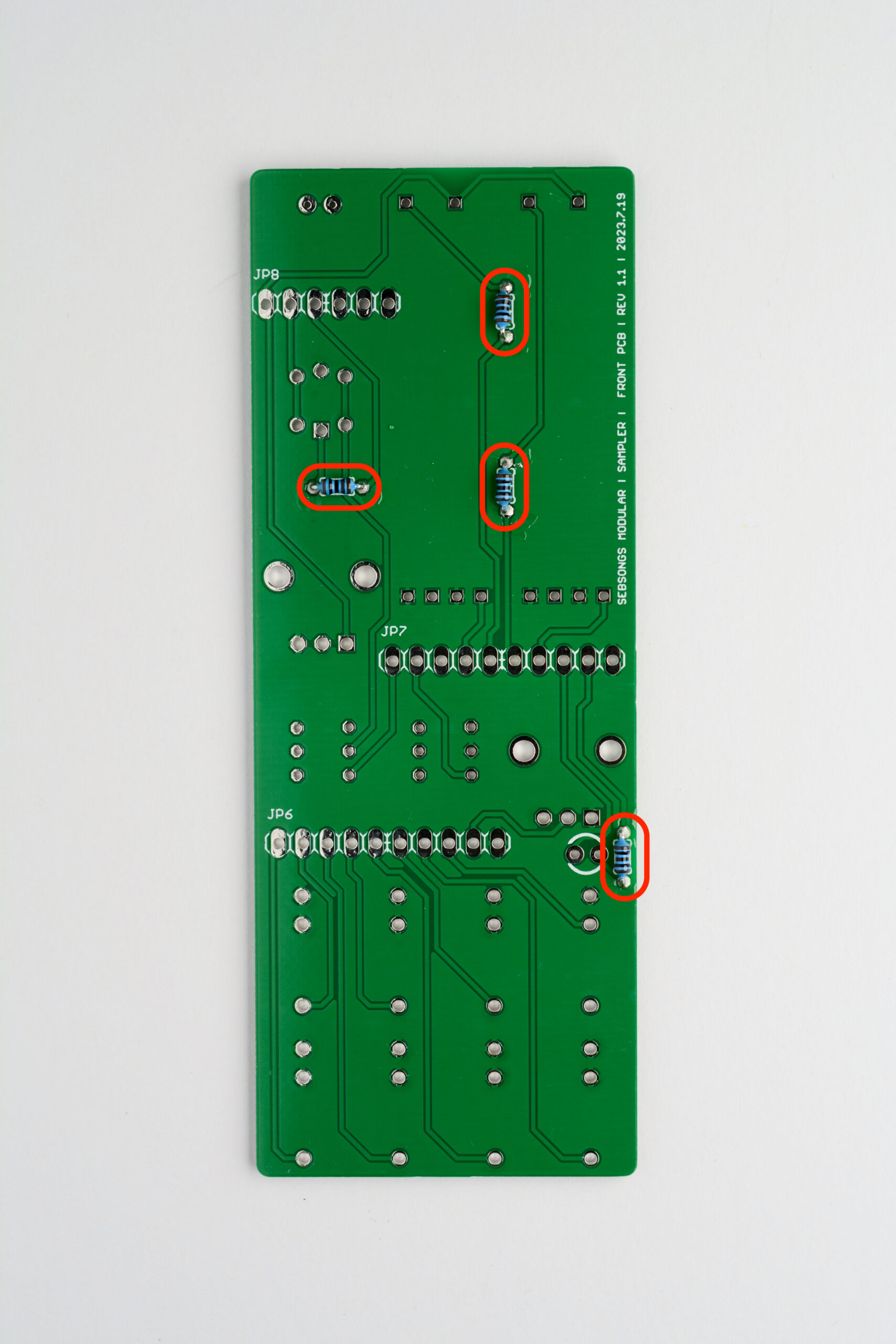
1. Resistors
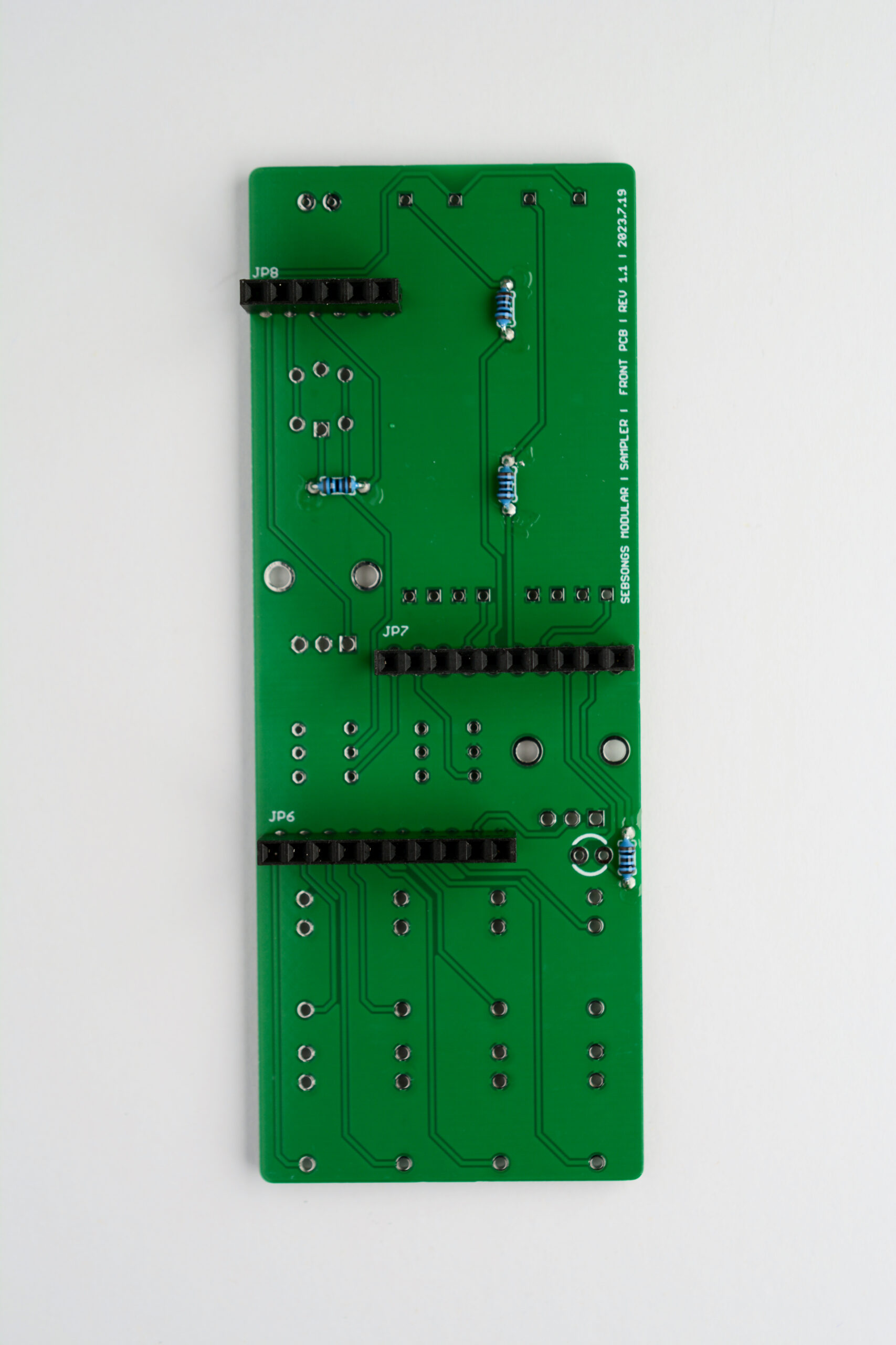
Solder the 100R resistors (R27, R28, R29, R30). See image for placement reference.
2. Headers
Connect the 10 and 6 pin recepticles to the pin headers of the BACK PCB. Carefully place the FRONT PCB on top and align the two PCBs as showed in the image above. Solder one pin on each pin header while taking care to keep the PCBs aligned. Check alignment again and then solder the rest of the pins.You should now have the pin recepticles solder nice and straigth onto the back of the FRONT PCB, as showed in the image above.
3. Fader LED replacement*
*NOTE: The faders that come with Thonk kits already have white LEDs and does not have to be changed. Skip this step if your fader LEDs are already clear colored!
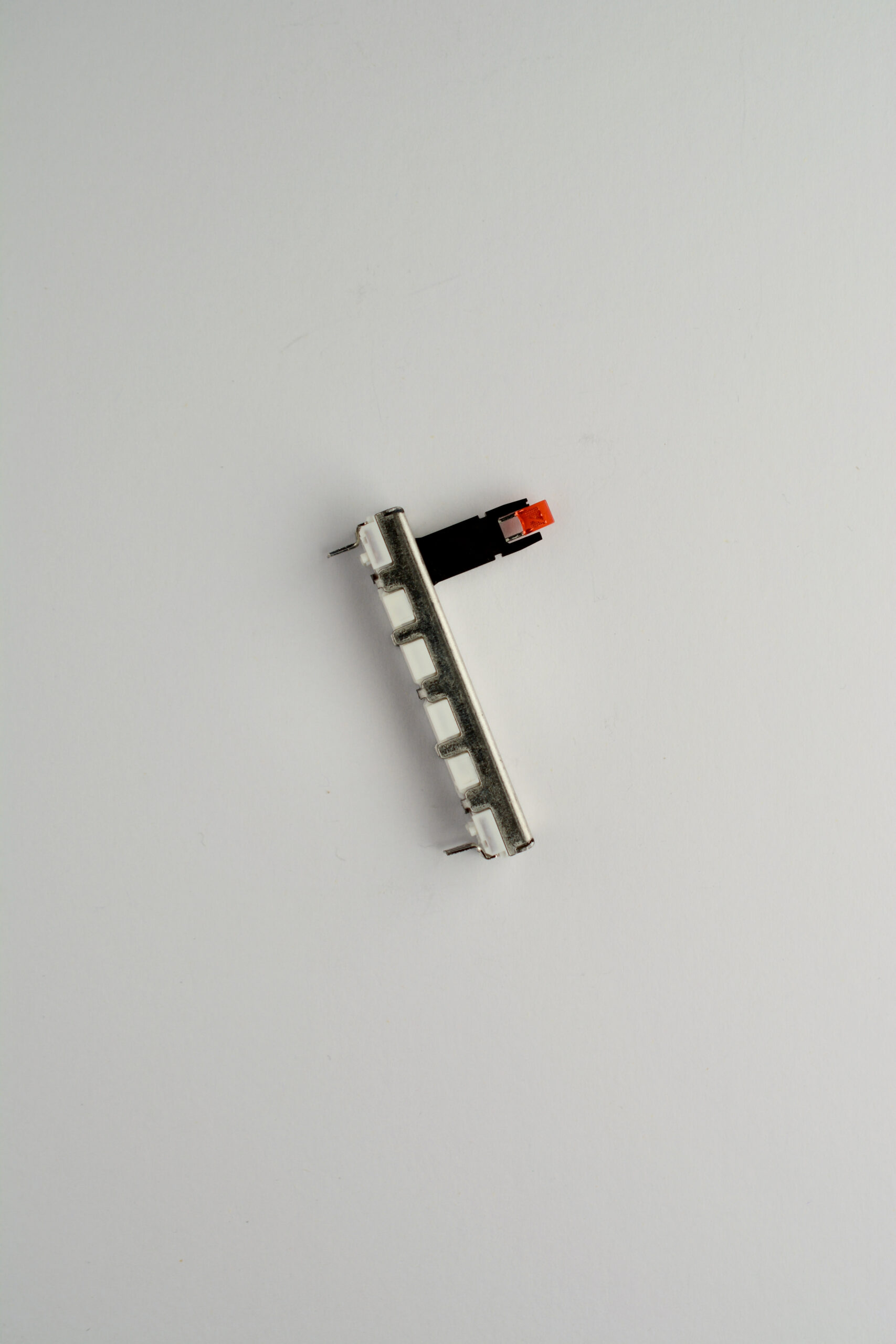
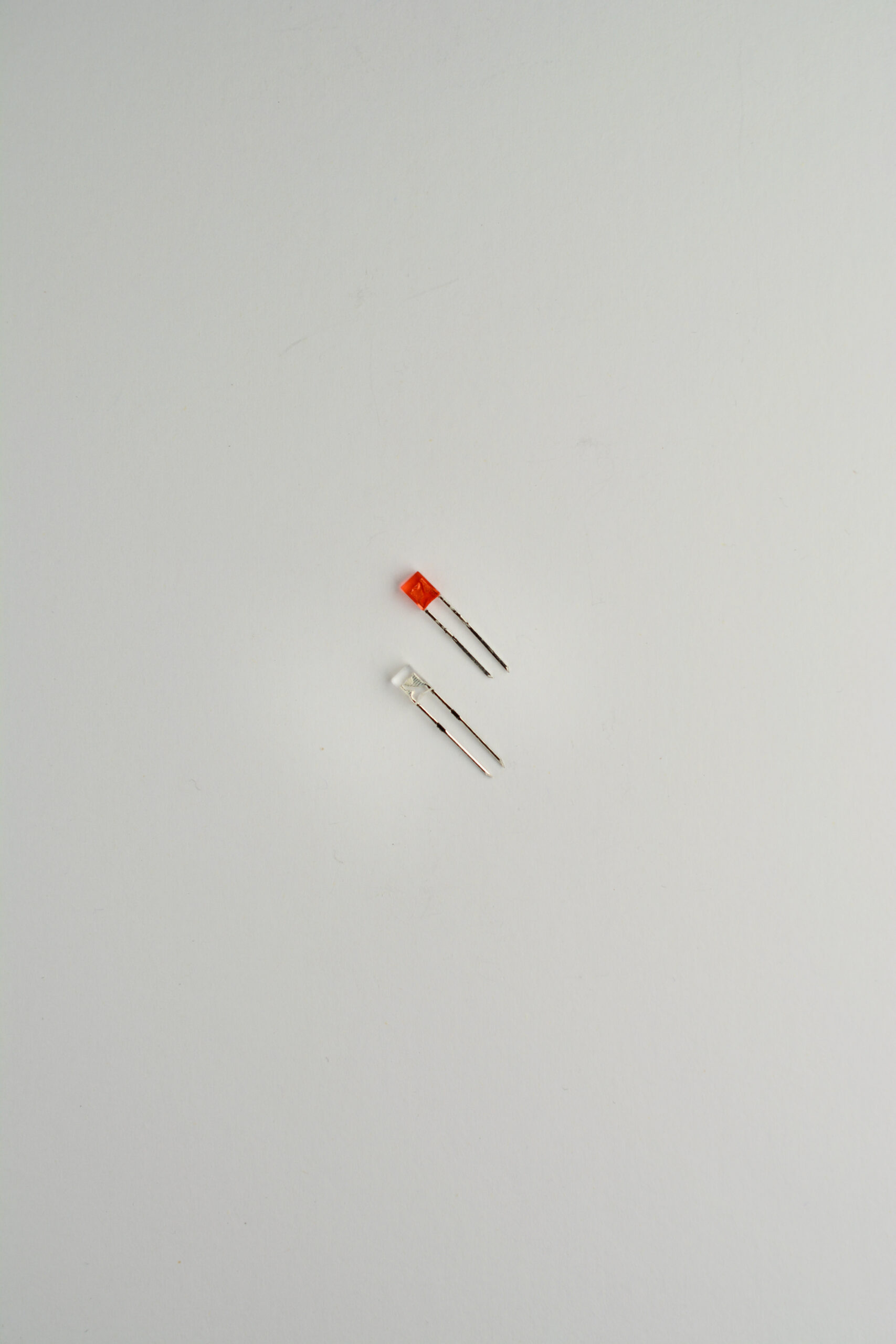
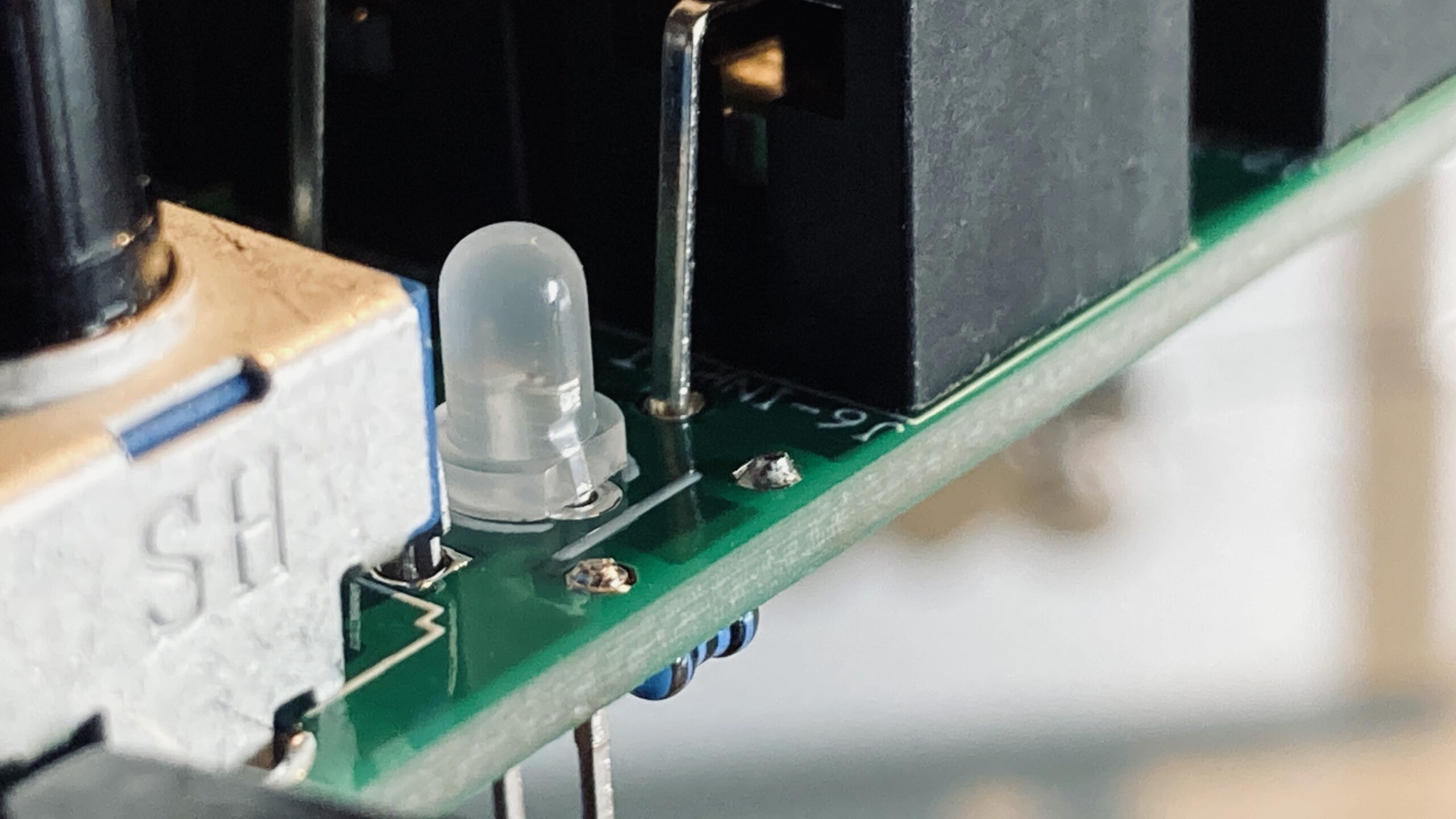
The kit comes with red LED faders that can be changed to white LEDs to get the correct appearance. The LEDs are easy to pull out of the fader shaft. The white LEDs have long legs that need to be cut. Align the white LED with the red and cut the legs to the same length. When replacing the fader LEDs in the fader shafts, take care to orient the correctly as shown in the image above.
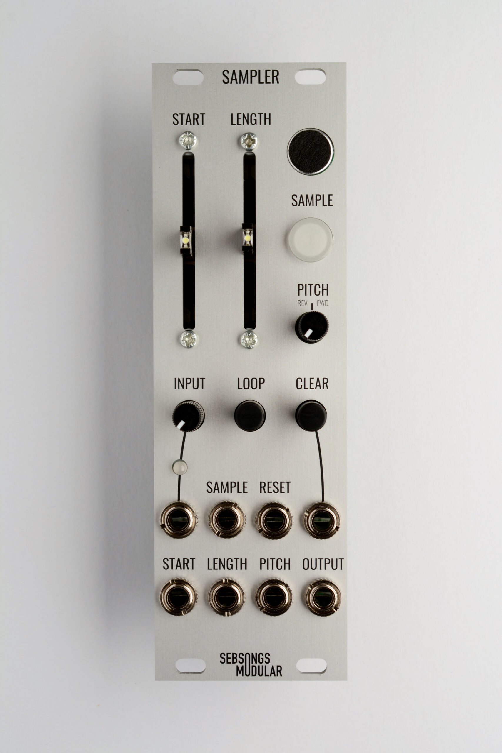
4. Jacks, switches and potentiometers and LED.
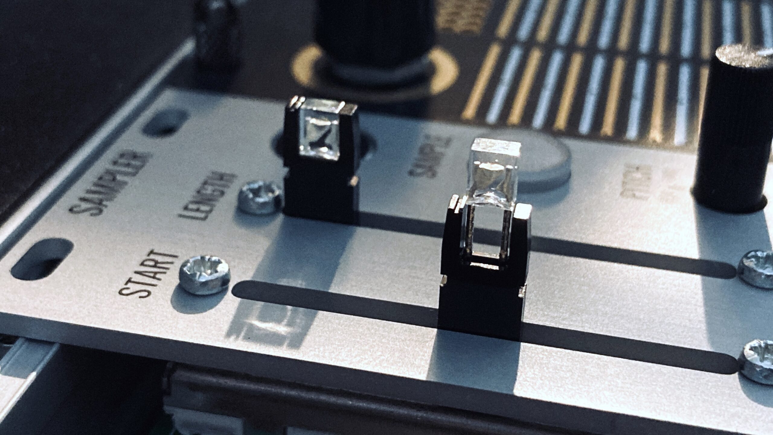
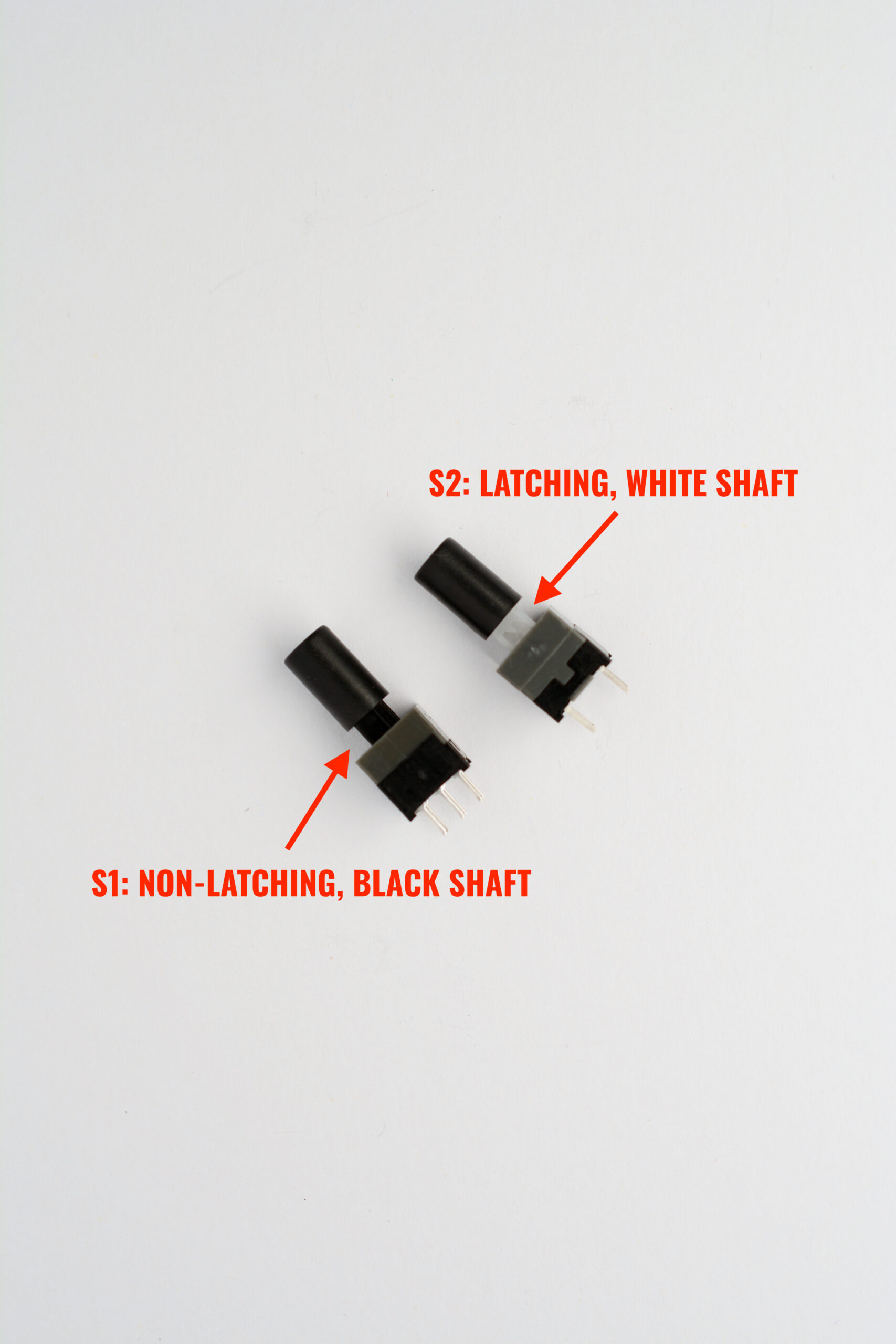
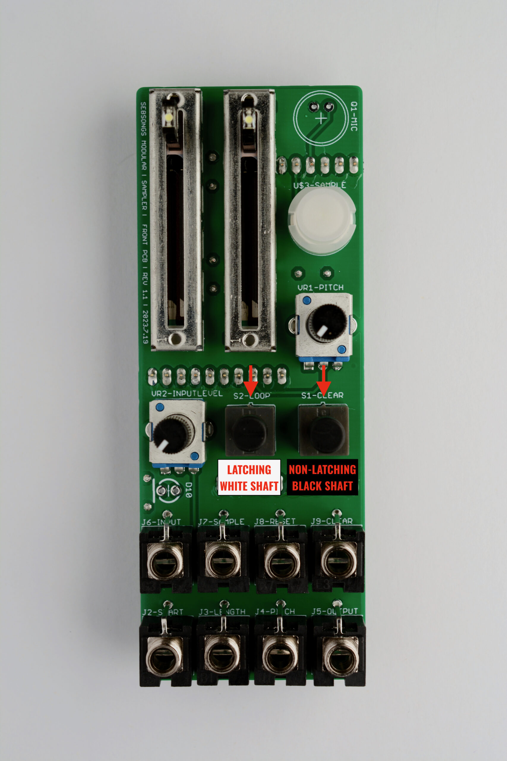
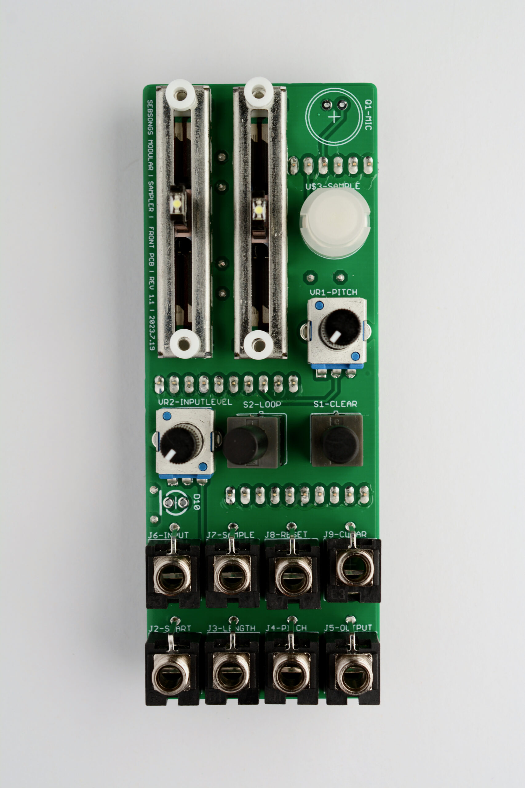
Now is a good time fit the caps on the two switches (S1, S2).Place the following components on the PCB without soldering them: – Jacks (J2-J9) – Non-latching switch with black shaft (S1) – Latching switch with white shaft (S2) – Illuminated switch (U$3) – Two 10kB faders (U$1, U$2) – 10kB tall trimmer potentiometer (VR1) – 10kA tall trimmer potentiometer (VR2). Make sure that the two switches S1 (non-latching, black shaft) and S2 (latching, white shaft) are placed correctly and have their protruding lines pointing up towards the faders, i.e. aligned with the silk screen!Carefully place and align the four white nylon spacers on top of the screw holes on the faders. Place the red/green LED (D10), minding its correct orientation. The flat edge and shorter leg must line up with the white line next to the LED. See image for reference. Carefully fit the front panel over the jacks, switches, faders and potentiometers, taking care not to disturb the nylon distances on the faders. Fit the four M2 screws in the holes above and below the faders and screw them in with a philips head screwdriver. Don’t over tighten them, just screw them in all the way without applying force. Finally, fit all the nuts for the jack sockets and hand tighten them, to hold the panel in place.Turn the whole assembly around and solder all the panel components while taking good care that the front panel aligns well with the PCB.. Remember to push the switches in while soldering them, or they will not fit correctly. Also make sure that the LED is correctly fitted in the front panel hole before soldering it.
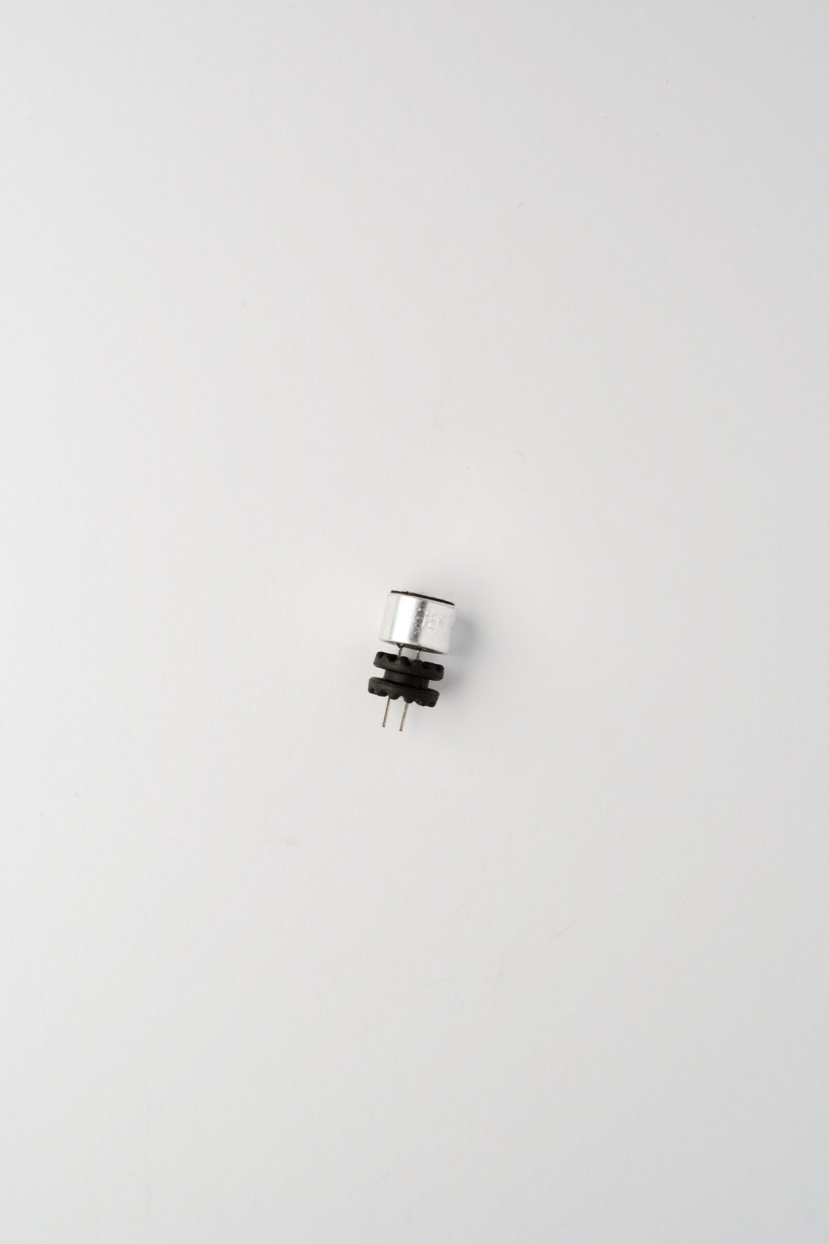
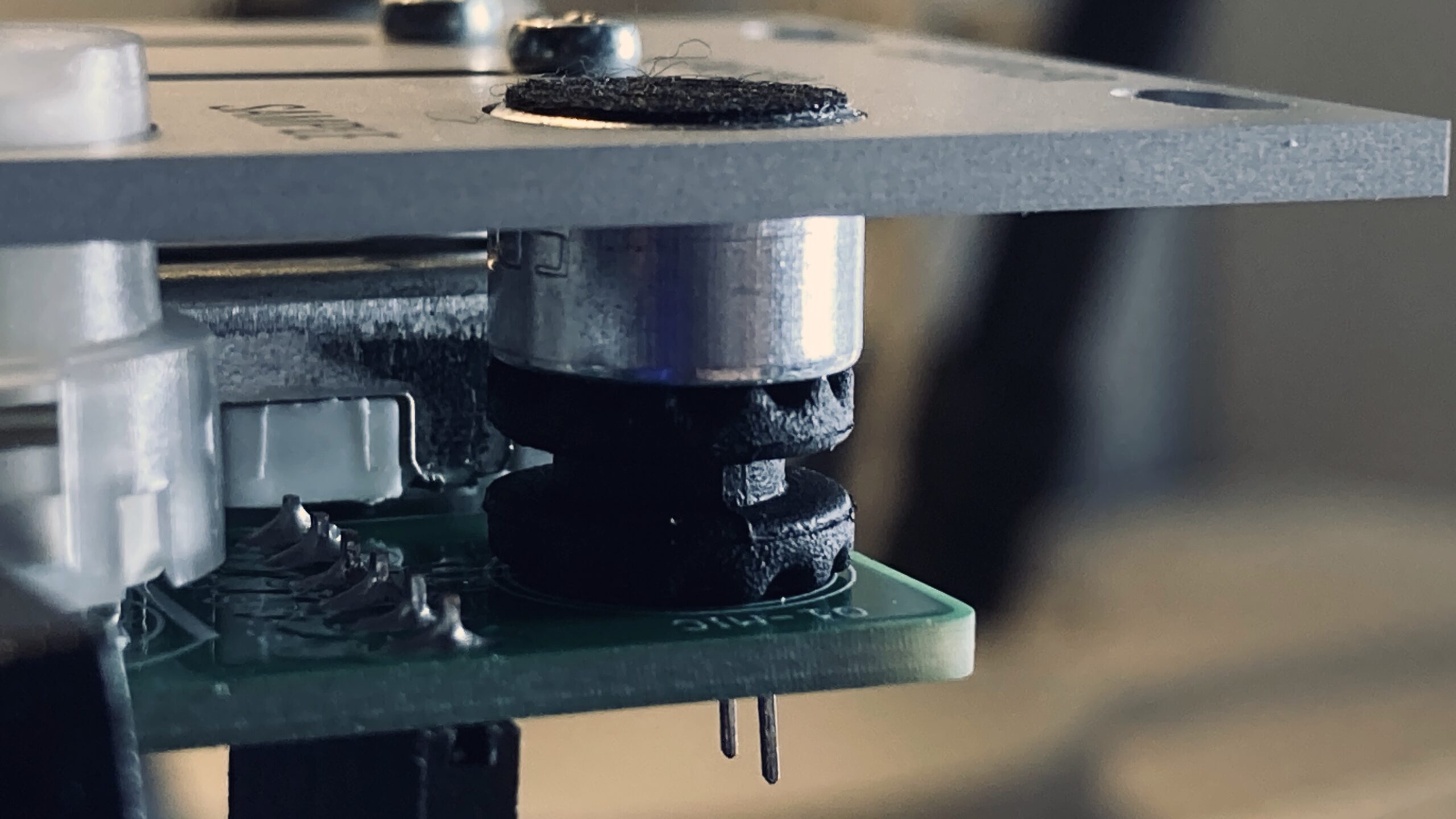
5. Microphone
Fit the legs of the microphone (Q1) in the hole of the rubber grommet as shown in the image above.Place the microphone on the PCB in its correct orientation. Push the microphone slightly agains the rubber grommet while soldering it, taking care that it aligns well with the front panel. The grommet is used both as a spacer and to dampen mechanical resonances.Finally, tighten the nuts for the jack sockets and the screws for the faders so the front panel is sufficiently secured. The FRONT PCB assembly is now finished and should look like this.
6. Finishing up
Connect the FRONT PCB to the BACK PCB via their pin headers and recepticles. You are now done with assembly of the Sebsongs Sampler!
6. Powering up and testing
Before powering on, measure resistance with a multimeter between ground and + and – respectively on the power connector to make sure there are no short circuits. The resistance should be several kilo Ohms and the value should climb as the multimeter charges the capacitors.