This build is an intermediate level build because of the relatively dense component placement. It is recommended that you start with something easier if you have never soldered before. However, with care and patience, this project should be straigth forward to do!
Do this before building this module:
Check that you have all components.
Gather all the tools needed (see lists below).
The tools needed for this build are:
Soldering station or soldering iron.
High quality solder (lead free recommended).
Fine tipped side cutters.
Round-nosed pliers (for bending component legs).
Recommended accessories:
PCB holder (makes life much easier).
Knurled Nut Driver Tool (for tightening jack socket nuts).
10 mm hex socket covered in masking tape (for tightening nuts).
Got everything? Let’s get on with it!
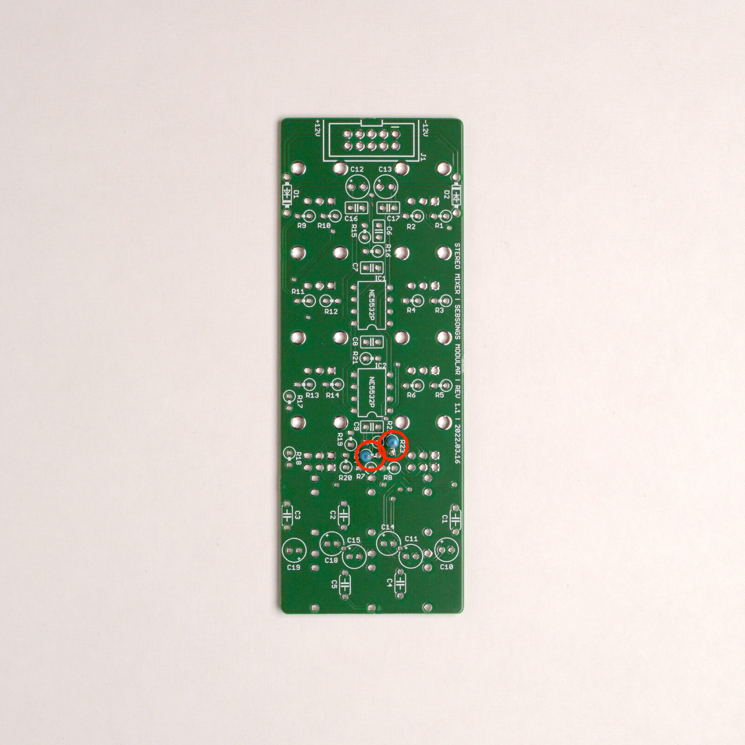
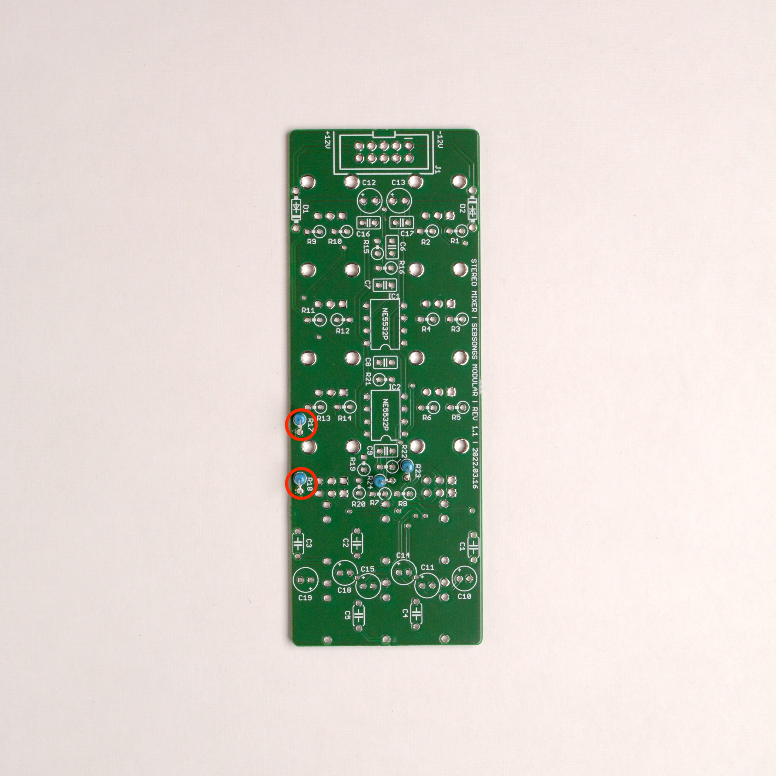
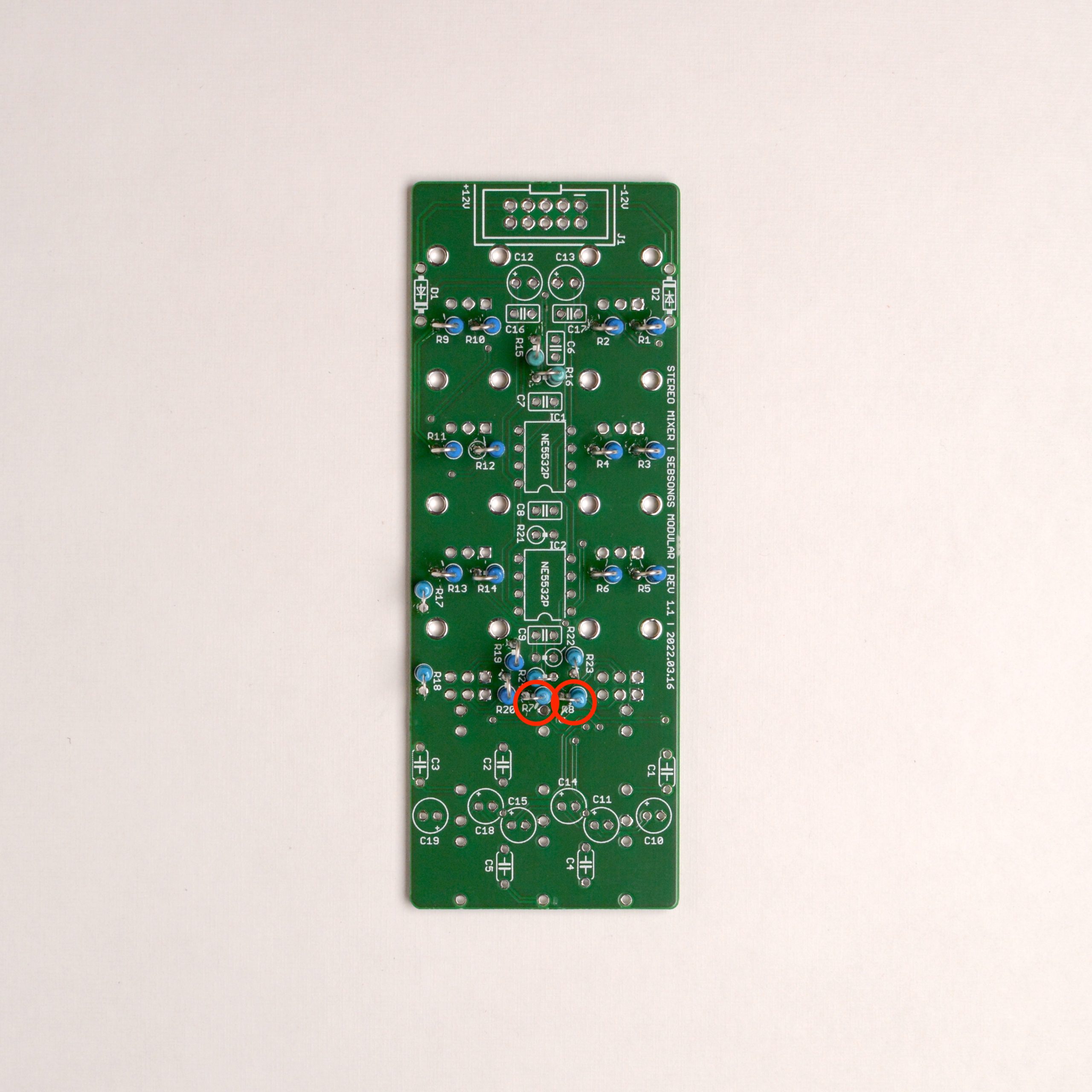
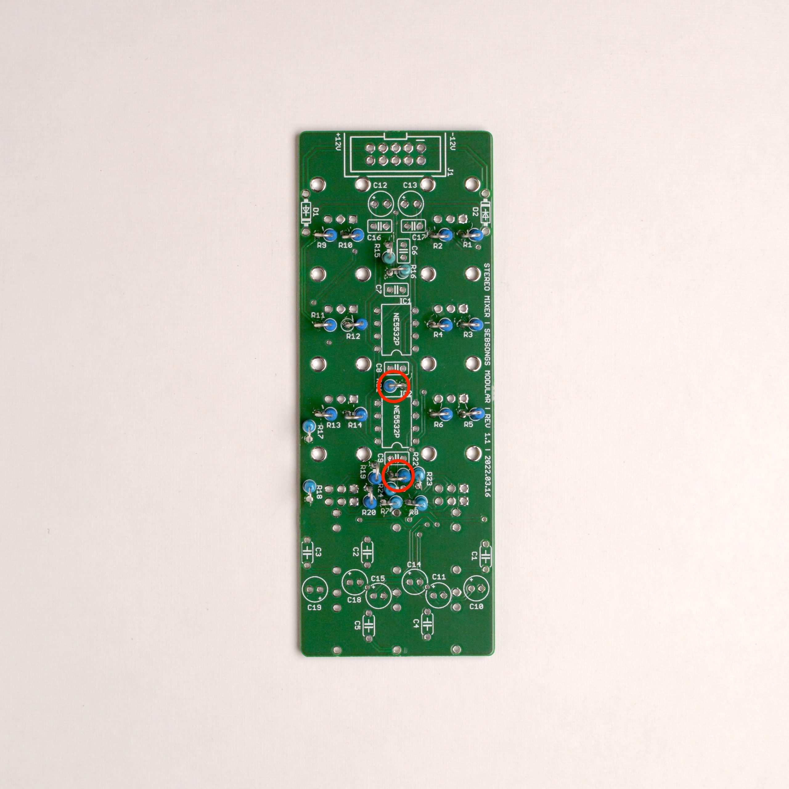
1. Resistors
Solder all 270R resistors (R23, R24). Bend one leg on each resistor in order to prepare them for standing assembly.Solder all 10K resistors (R17, R18). Bend one leg on each resistor in order to prepare them for standing assembly.Solder all 20K resistors (R1, R2, R3, R4, R5, R6, R9, R10, R11, R12, R13, R14, R19, R20). Bend one leg on each resistor in order to prepare them for standing assembly.Solder all 39K resistors (R15, R16). Bend one leg on each resistor in order to prepare them for standing assembly.Solder all 51K resistors (R7, R8). Bend one leg on each resistor in order to prepare them for standing assembly.Solder all 100K resistors (R21, R22). Bend one leg on each resistor in order to prepare them for standing assembly.
2. Capacitors
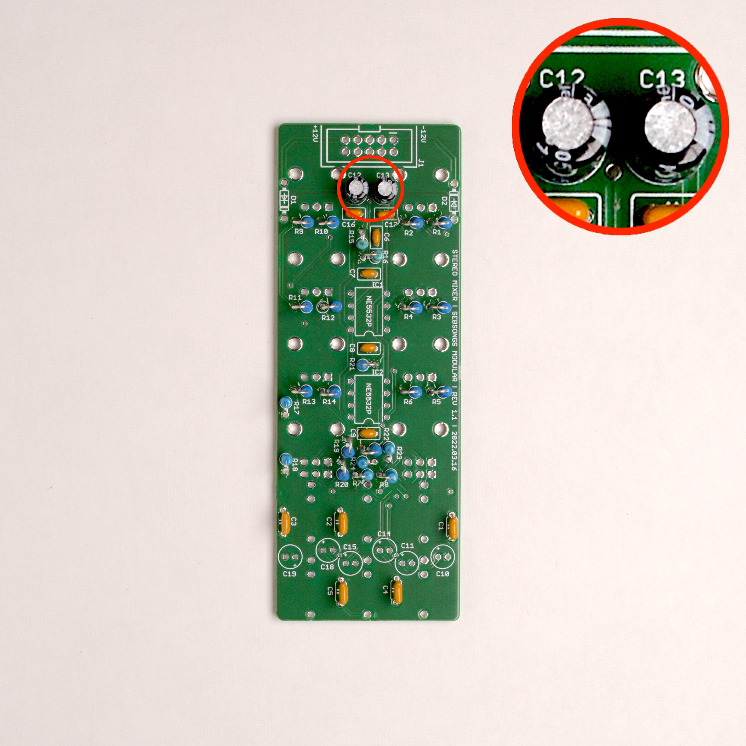
Solder the 22pF ceramic capacitors (C6, C7, C8, C9).Solder the 100nF ceramic capacitors with 2.5 mm pitch (C16, C17).Solder the 100nF ceramic capacitors with 5 mm pitch (C1, C2, C3, C4, C5).Solder the 10uF electrolytic capacitors (C12, C13). Make sure to check the polarity twice before soldering, the long leg must go to the hole with the plus symbol! See image for reference.Solder the 33uF electrolytic capacitors (C10, C11, C14, C15, C18, C19). All capacitors have their negative side to the right except the leftmost capacitor C19 which is mirrored. Make sure to check the polarity twice before soldering, the long leg must go to the hole with the plus symbol! See image for reference.
3. Diodes
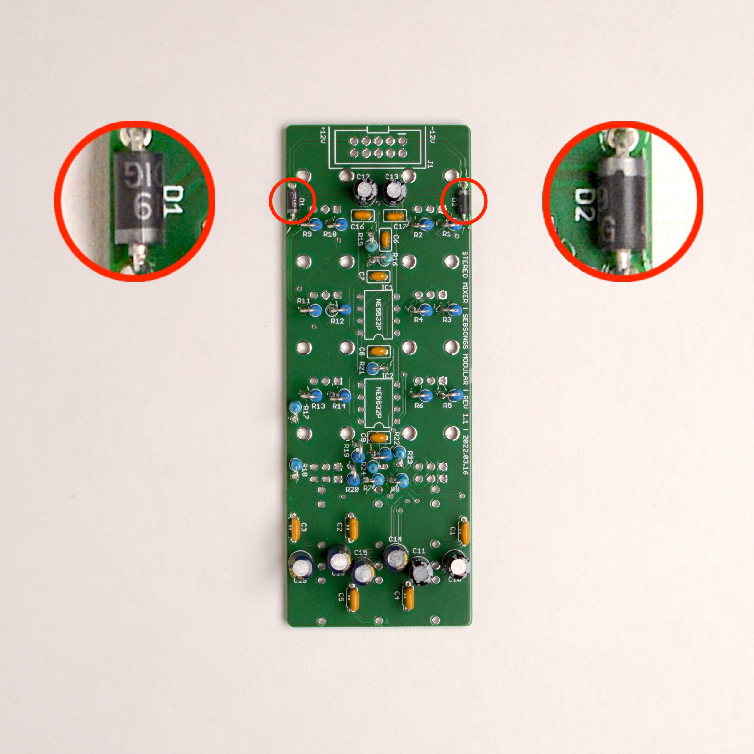
Solder the 1N5819 schottky diodes (D1, D2). Make sure to check the polarity twice before soldering! See image for reference.
4. Headers and IC sockets
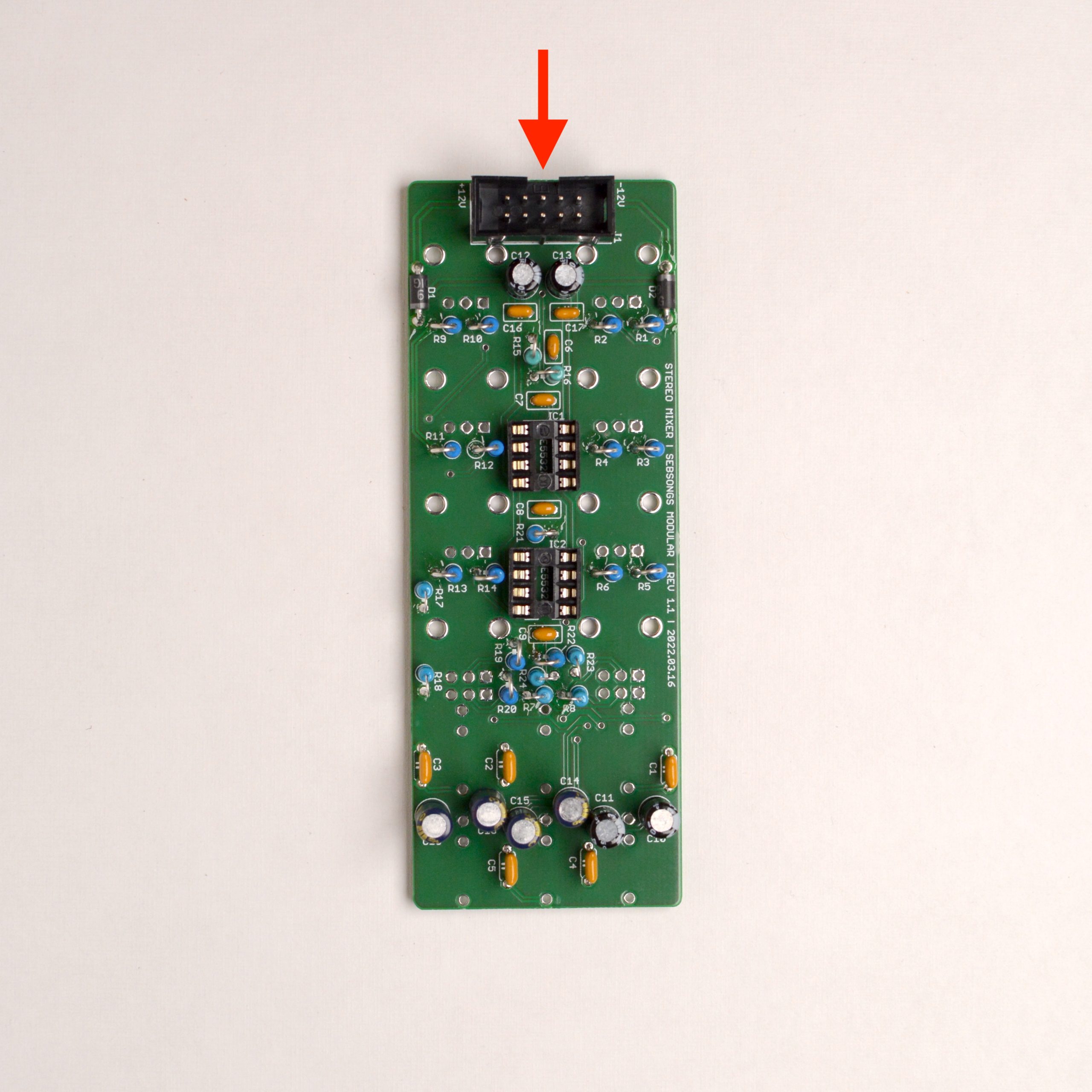
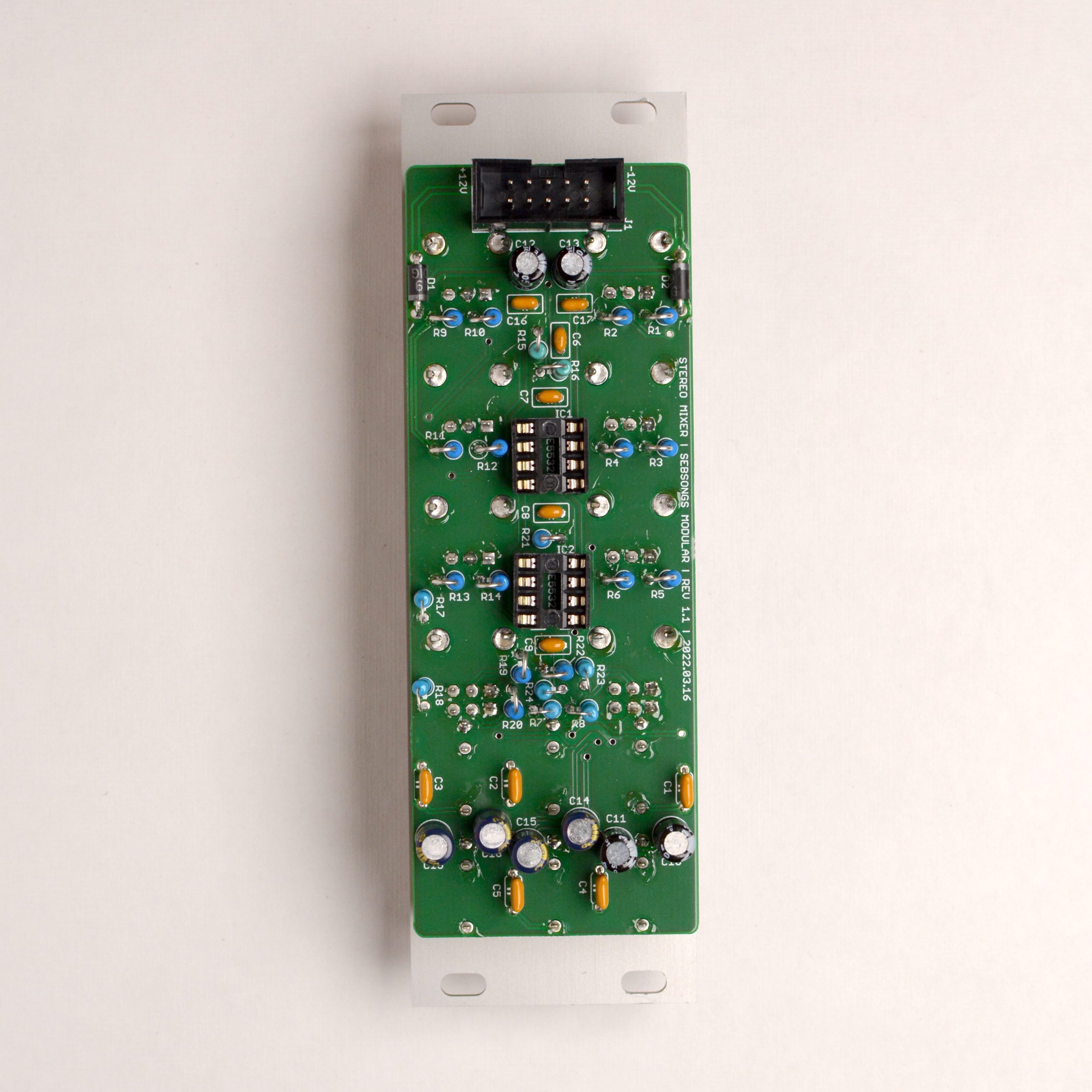
Solder the two 8 pin IC sockets (IC1, IC2). Make sure to check the orientation twice before soldering! See image for reference.Solder the 2×5 pin header for the eurorack power connector. Make sure to check the orientation twice before soldering! See image for reference.
5. Jacks sockets and potentiometers
Place the A100K potentiometers (VR1, VR2, VR3), the dual A100K potentiometers (VR4, VR8) and the B50K potentiometers (VR5, VR6, VR7). Also place the black mono jack sockets (U1, U2, U3, U4, U5) and the green stereo jack socket (U6). Do not solder them yet!Attach the front panel, place the washers for the potentiometers and all the nuts for both potentiometers and jack sockets. Hand tighten all the nuts. Make sure everything is straigth and correctly seated. Solder all the joints for the potentiometers and jack sockets. Take care not to damage any components when soldering! Take extra care between the bottom electrolytic capacitors as these are quite a tight fit. If you have a thinner solder tip, use that in the tight spots, or angle your soldering tip to make it as narrow as possible.
6. Opamps
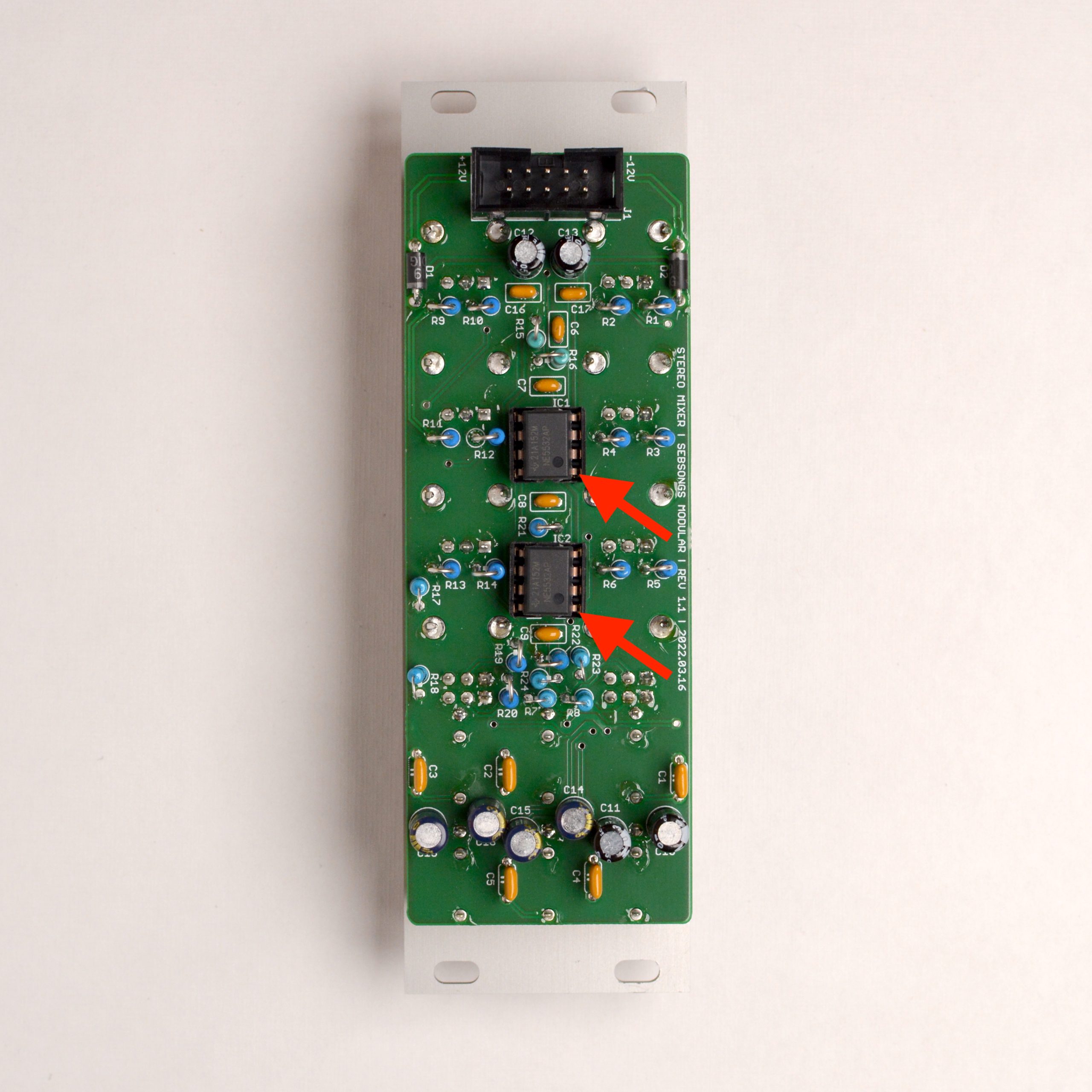
Seat the opamps in the IC sockets. Make sure to carefully bend the pins beforehand so they are 90 degrees – this makes it easier to fit them in the sockets. Make sure to check the orientation twice before fitting them in their sockets! Pin 1 must be oriented where the arrow points in the image above. Click the image to see a larger version.
7. Final touches
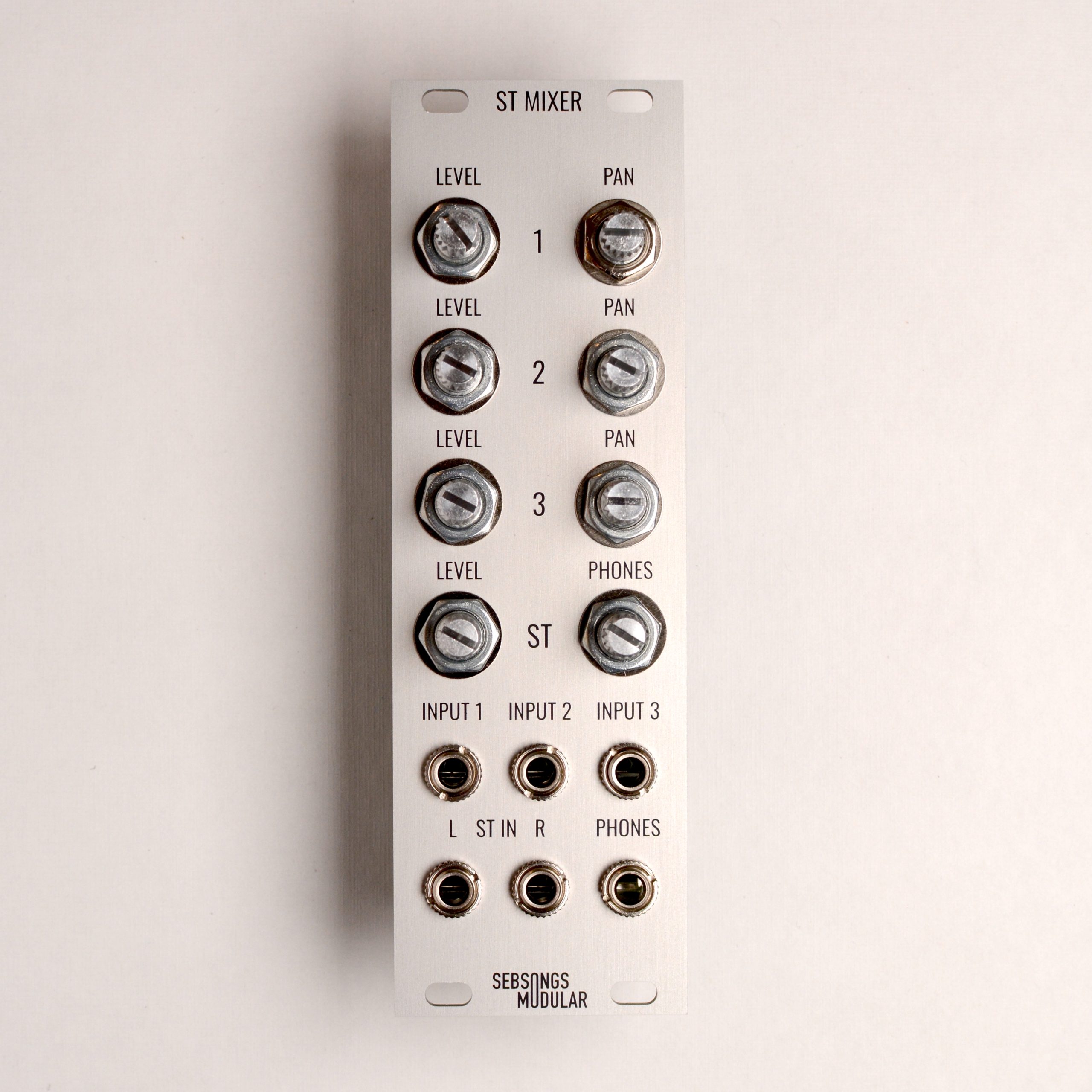
Tighten all the nuts with appropriate tools, taking care not to scratch the front panel. Mount the knobs on the potentiometer shafts. Now you are done! Connect the module to power in a eurorack case and power it up. Connect a pair of headphones to the PHONES output and connect an oscillator to INPUT 1. Increase the level for channel 1 and test the panning left and right.