This build is a intermediate level build with quite a bit of surface mount components. Don’t do this as your first surface mount project, as it is quite large and time consuming. However, if you have done some SMD work before, this build should be very straight forward.
Do this before building this module:
Check that you have all components.
Gather all the tools needed (see lists below).
The tools needed for this build are:
Soldering station or soldering iron.
High quality solder (lead free recommended).
Angled tweezers for surface mounting.
Recommended accessories:
PCB holder (makes life much easier).
Knurled Nut Driver Tool (for tightening jack socket nuts).
10 mm hex socket covered in masking tape (for tightening potentiometer nuts).
Got everything? Let’s get on with it!
1. ICs
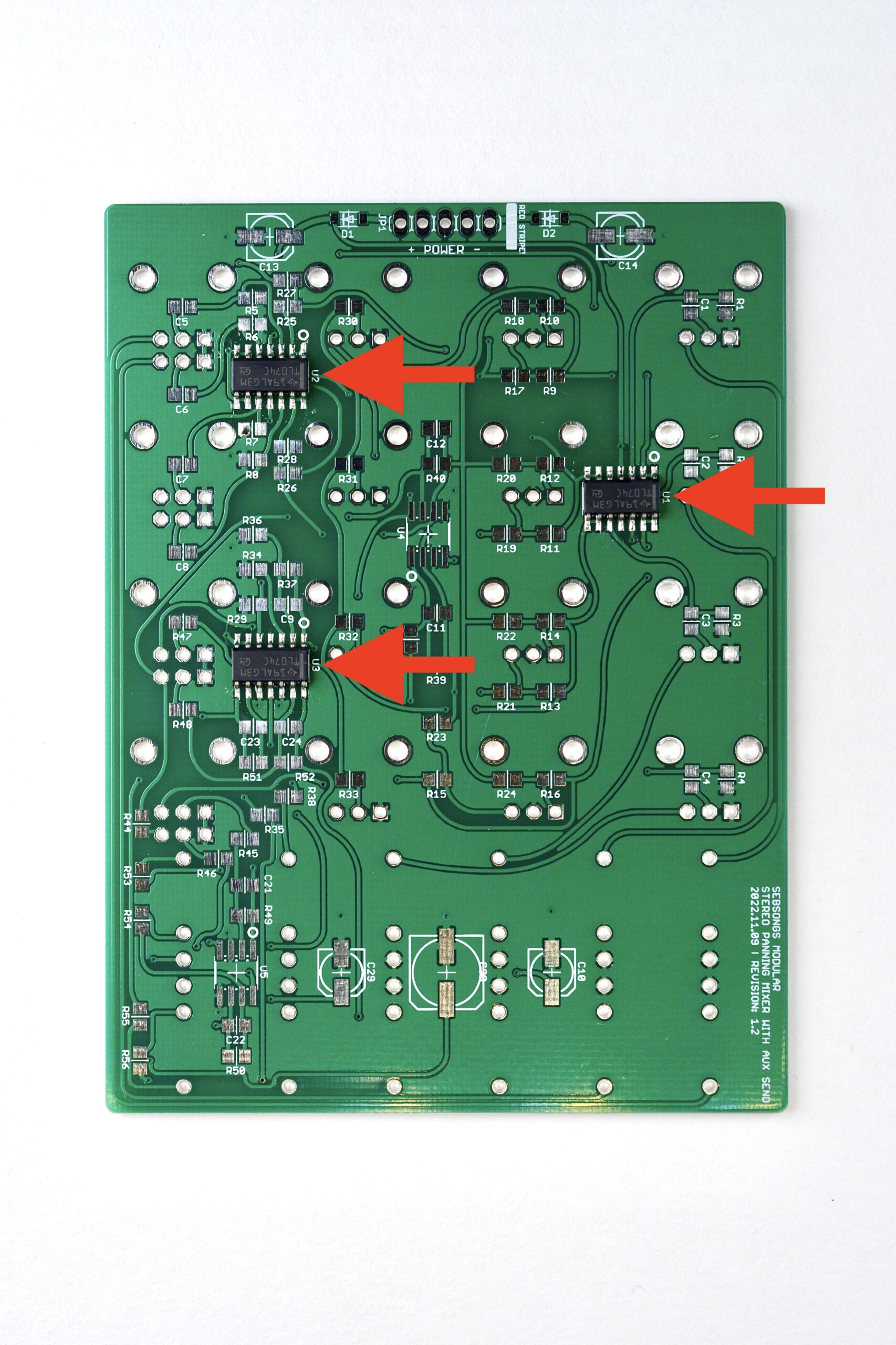
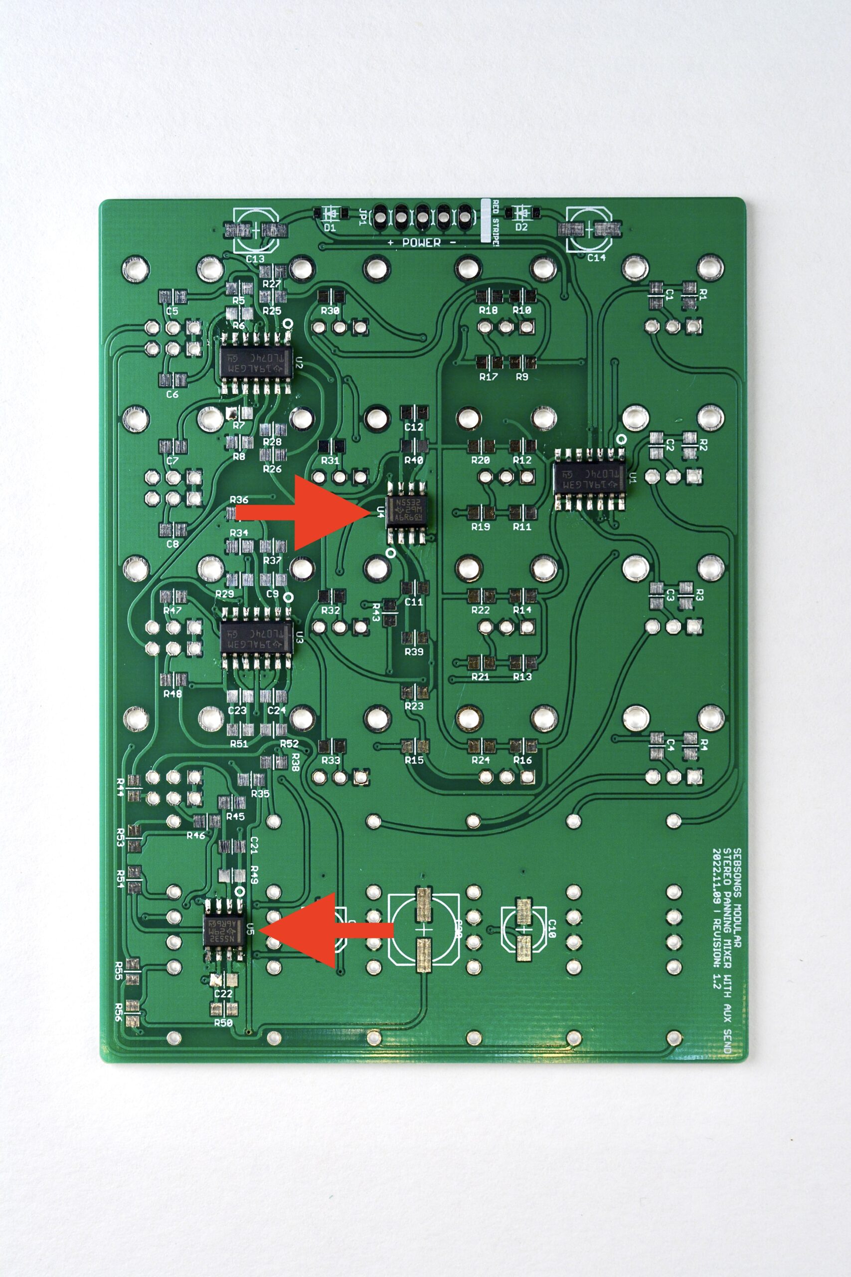
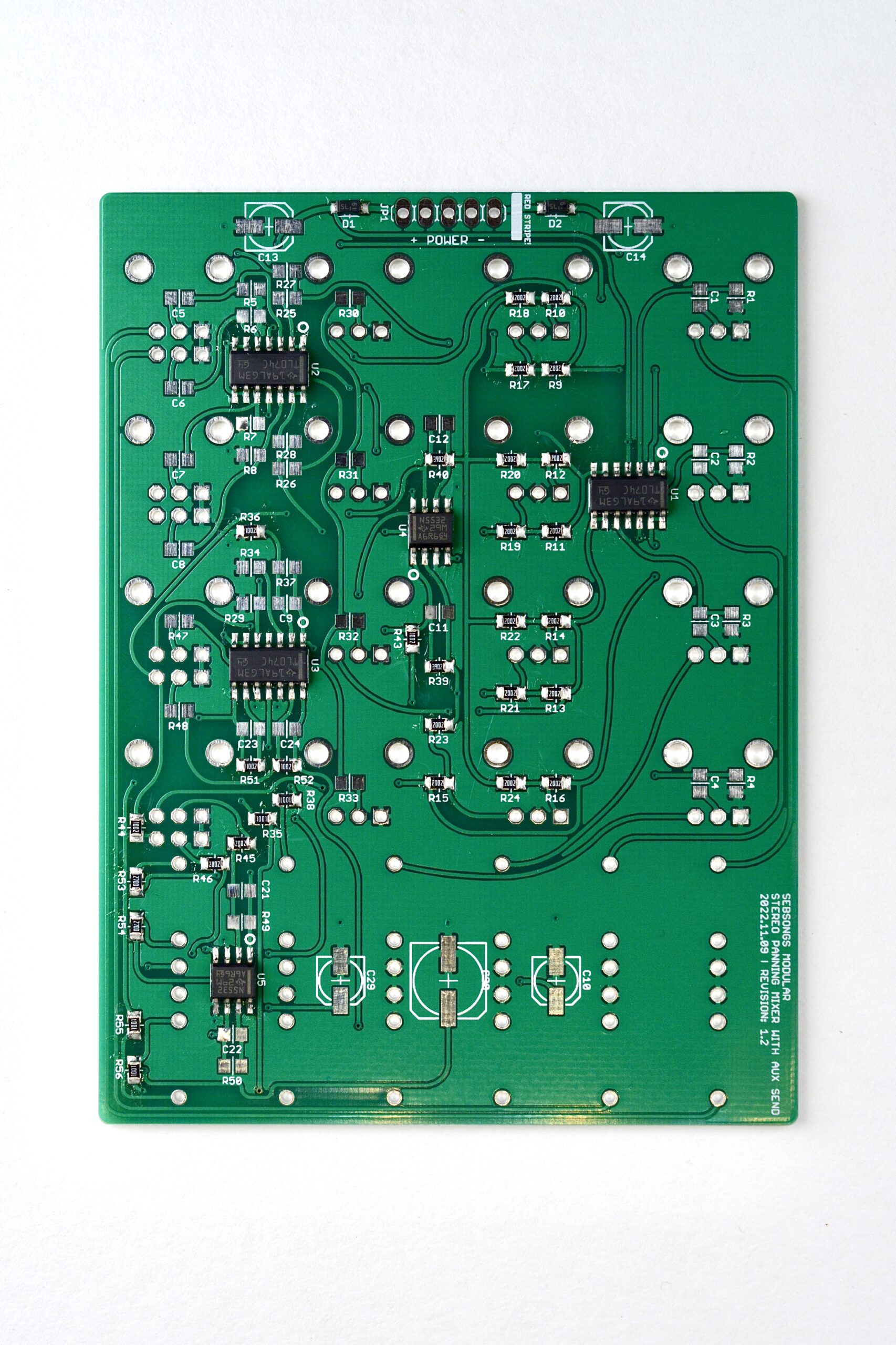
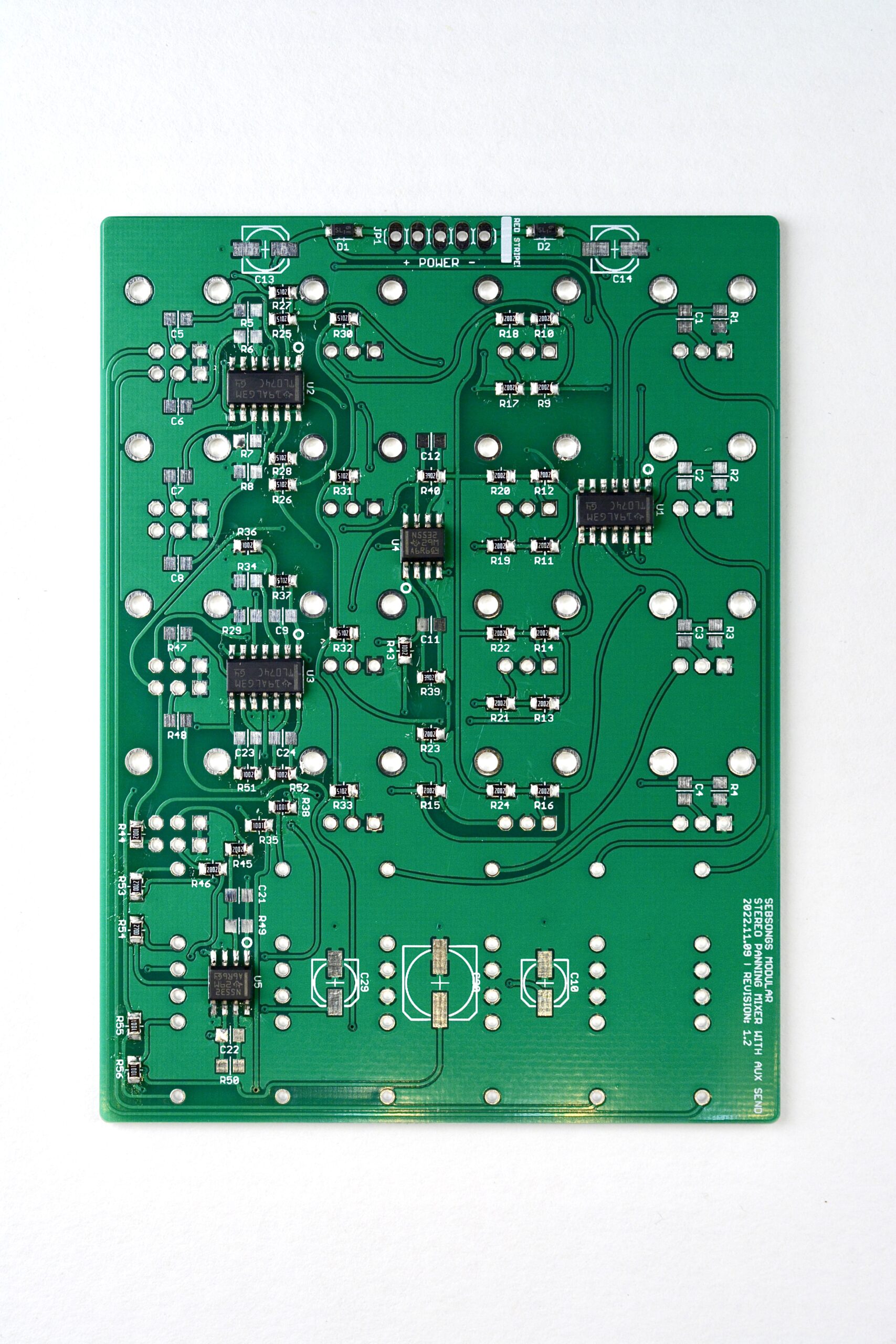
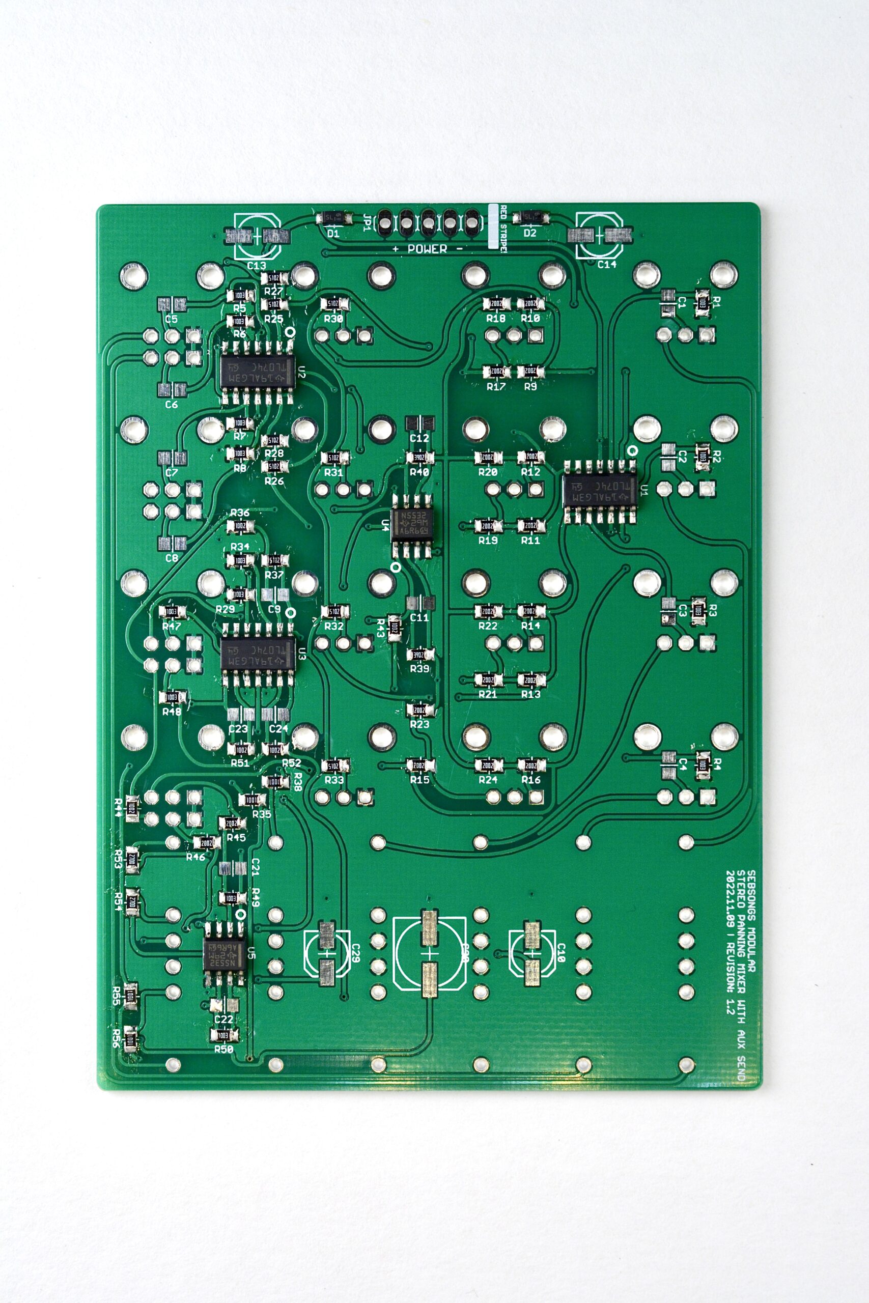
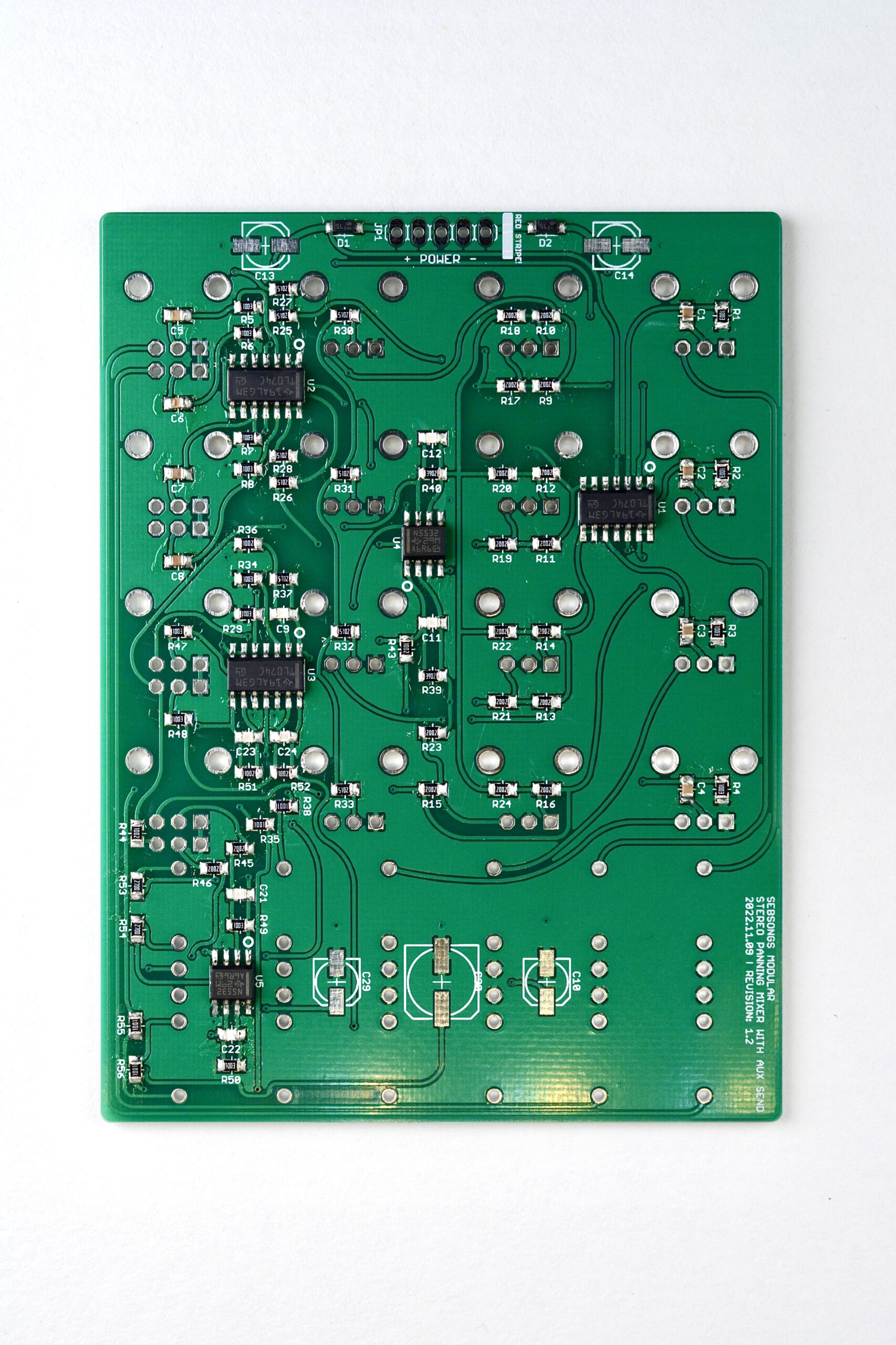
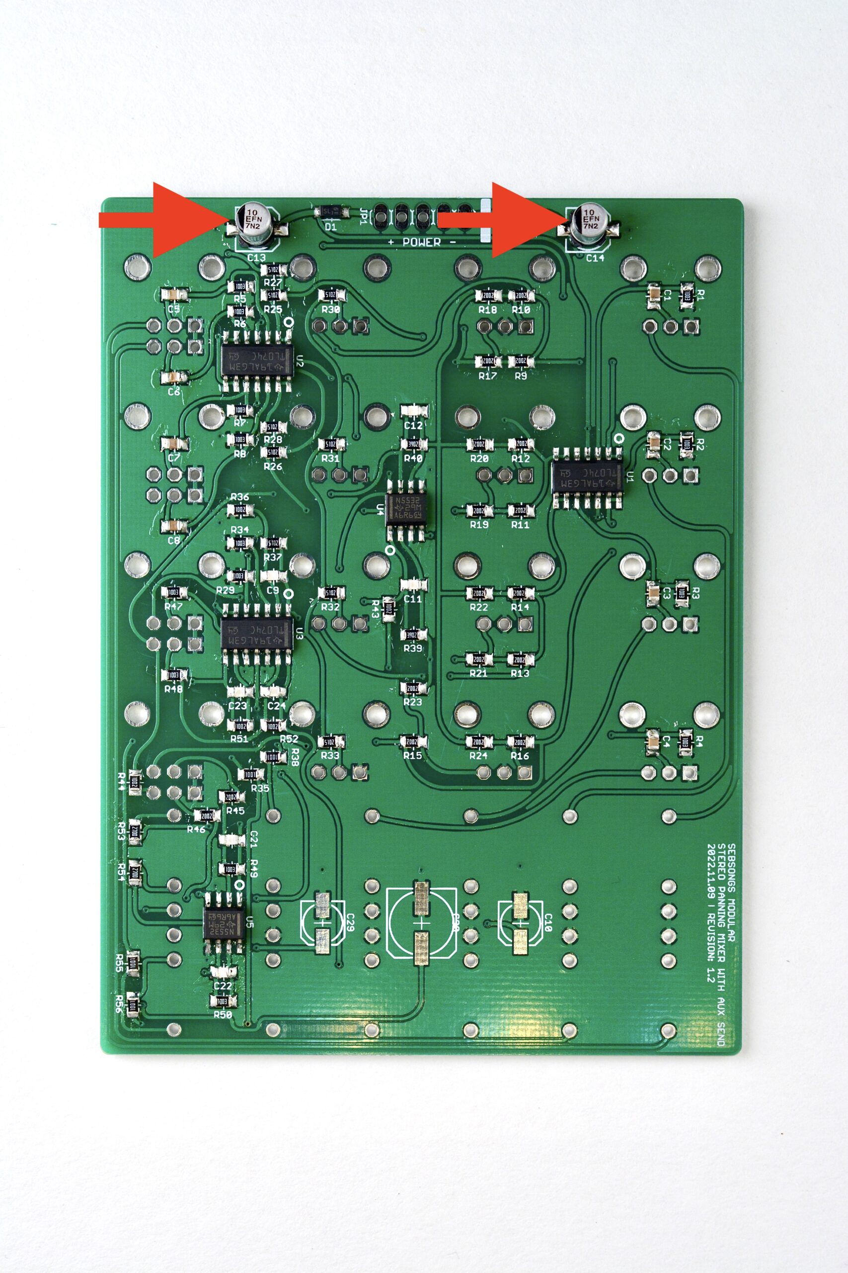
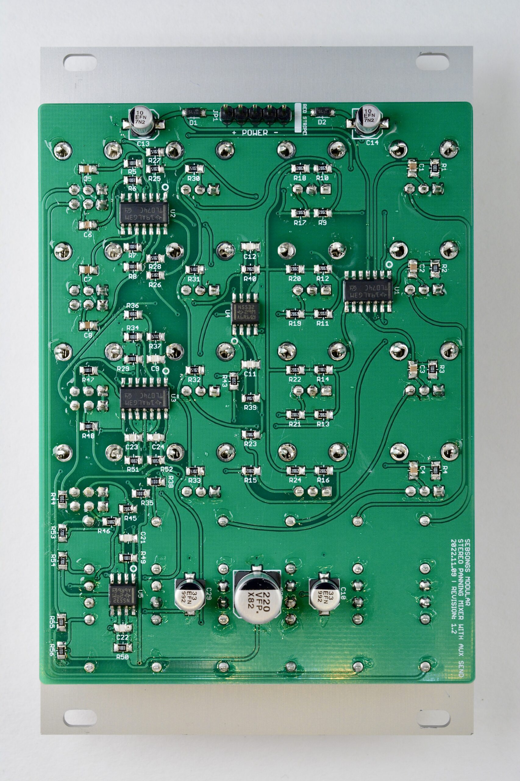
Solder all TL074 operational amplifiers (U1, U2, U3). Make sure to check the orientation twice before soldering! See image for reference.Solder the two NE5532 operational amplifiers (U4, U5). Make sure to check the orientation twice before soldering! See image for reference.
2. Diodes
Solder the 1N5819 schottky diodes (D1, D2). Make sure to check the polarity twice before soldering! See image for reference.
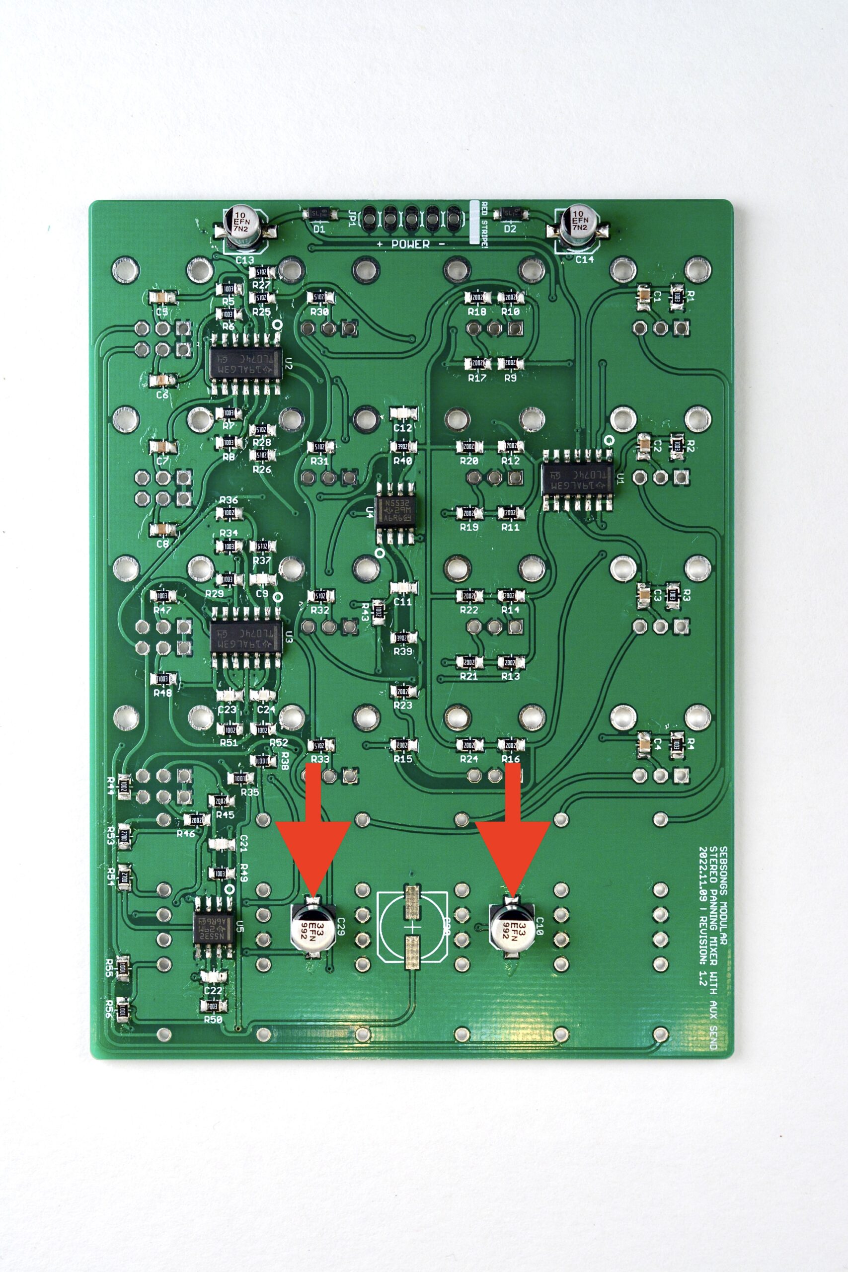
Solder the 22pF ceramic capacitors (C9, C11, C12, C21, C22, C23, C24).Solder the first eight 100nF ceramic capacitors (C1, C2, C3, C4, C5, C6, C7, C8).Flip the board over and solder the rest of the 100nF ceramic capacitors (C15, C16, C17, C18, C19, C20, C25, C26, C27, C28).Solder the 10uF electrolytic capacitors (C13, C14). Make sure to check the polarity twice before soldering! See image for reference.Solder the 33uF electrolytic capacitors (C10, C29). Make sure to check the polarity twice before soldering! See image for reference.Solder the large 220uF electrolytic capacitor (C30). Make sure to check the polarity twice before soldering! See image for reference.
5. Power header
Solder the 1×5 pin power header.
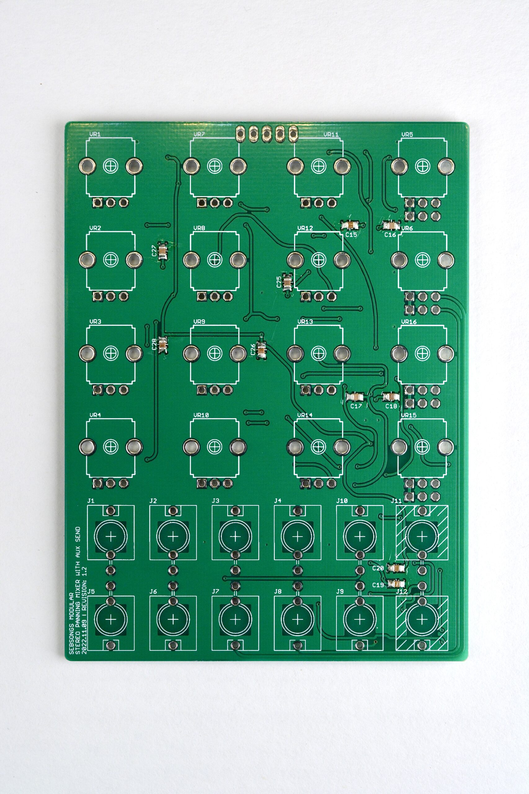
6. Jacks sockets and potentiometers
Place the A100K potentiometers (VR1, VR2, VR3, VR4, VR11, VR12, VR13, VR14), the dual A100K potentiometers (VR5, VR6, VR15, VR16) and the B50K potentiometers (VR7, VR8, VR9, VR10). Also place the black mono jack sockets (J1, J2, J3, J4, J5, J6, J7, J8, J9, J10) and the green stereo jack sockets (J11, J12). Do not solder them yet!Attach the front panel, place the washers for the potentiometers and all the nuts for both potentiometers and jack sockets. Hand tighten all the nuts. Make sure everything is straigth and correctly seated. Solder all the joints for the potentiometers and jack sockets. Take care not to damage any components when soldering! Take extra care between the bottom electrolytic capacitors as these are quite a tight fit. If you have a thinner solder tip, use that in the tight spots, or angle your soldering tip to make it as narrow as possible.
7. Final touches
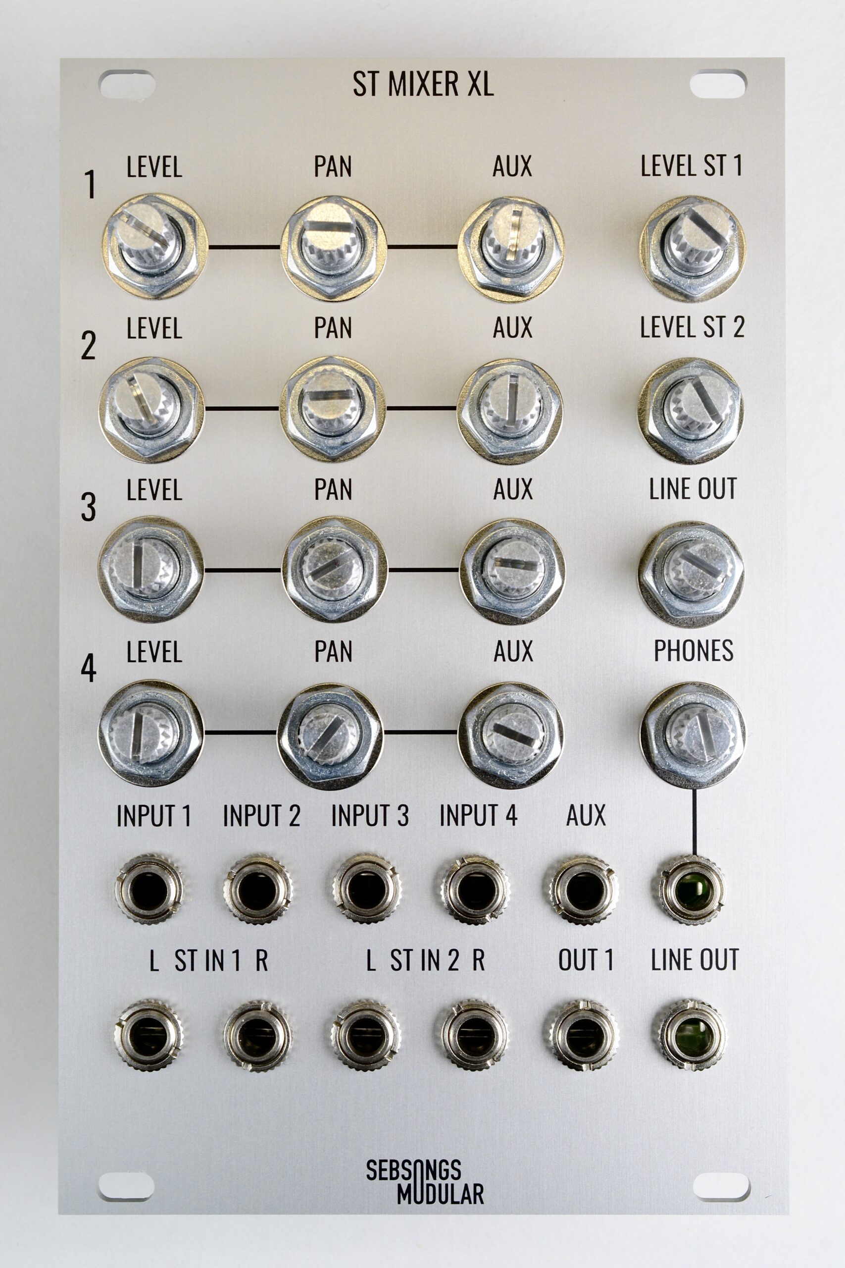
Tighten all the nuts with appropriate tools, taking care not to scratch the front panel. Mount the knobs on the potentiometer shafts. Now you are done! Connect the module to power in a eurorack case, making sure you orient the power connector correctly (white line on PCB aligns with red strip on power cable) and power it up. Connect a pair of headphones to the PHONES output and connect an oscillator to INPUT 1. Increase the level for channel 1 and the headphone output, and test the panning left and right. Test all inputs and outputs to see that everything works. You’re now done!